
Create Two Node HA Infrastructure for Load Balancing Using Virtual Sites with Customer Edges
Objective
This guide shows you how to achieve high availability (HA) of a CE with two single-node CE sites grouped into a single logical entity, a Virtual Site (vSite), and how to use this vSite for application delivery services for your apps. This guide also describes the use cases for application delivery using vSite deployment.
Introduction
For production deployments, F5 recommends you deploy a three-node CE Site for high availability (HA). In this model, the Secure Mesh Site software is deployed on three separate nodes, and they are clustered to operate as a single CE Site. However, this may not be suitable for every customer deployment. For example:
-
If a data center has two AZs, then it is more logical to deploy a CE in each AZ than deploying a three-node CE with one node in one AZ and two nodes in the other.
-
If you want to guarantee resiliency against upgrade issues, then you can upgrade one CE Site at a time, ensuring the other is up to serve the traffic.
For these scenarios, the recommended alternative approach is to group two single-node CE sites into a single logical entity – a vSite. This vSite can be leveraged to provide application delivery services for your apps.
Prerequisites
The following general prerequisites apply:
-
A Distributed Cloud Services Account. If you do not have an account, see Getting Started with Console.
-
Allow traffic from and to the Distributed Cloud public IP addresses to your network and allowlist related domain names. See Firewall and Proxy Server Allowlist Reference guide for the list of IP addresses and domain names.
-
The CE sites must follow the Secure Mesh Site v2 workflow using the following procedure: Create Secure Mesh Site v2.
-
For public cloud providers, additional manual configuration of cloud provider-specific load balancers may be required.
-
Ensure that the two CE sites (that are part of the vSite) are deployed in the same network domain. This implies the following:
- For public clouds: CE sites are within the same VPC/VNet.
- For on-premises: Each interface of the CE Sites is within the same Layer 2 broadcast domain.
-
Ensure that any CE Site within a vSite can communicate seamlessly with the clients or origin servers in the same vSite.
Important: After you deploy the CE Site, the IP address for the SLO interface cannot be changed. Also, the MAC address cannot be changed.
Procedure
This guide shows you how to configure high availability with two single-node CE sites aggregated as a single vSite and how to use this vSite for application delivery services for the apps.
Configure Virtual Site
This section shows you how to create a vSite using two single-node CE sites.
Deploy CE Sites
Create two single-node CE sites in the same VPC/VNet or local network domain. Each CE Site must have two interfaces: a Site Local Outside (SLO) for external connectivity and a Site Local Inside (SLI)/segment for origin servers.
As an example, this guide creates two CE sites in AWS, which are called pg-aws-vsite-2a and pg-aws-vsite-2b.
Refer to this document for creating CE sites: Create Secure Mesh Site v2.
- For AWS, deploy each Site using the procedure here: Deploy Secure Mesh Site v2 in AWS (ClickOps).
- For Azure, deploy each Site using the procedure here: Deploy Secure Mesh Site v2 in Azure (ClickOps).
- For GCP, deploy each Site using the procedure here: Deploy Secure Mesh Site v2 in GCP (ClickOps).
- For KVM, deploy each Site using the procedure here: Deploy Secure Mesh Site v2 on KVM (ClickOps).
Create Virtual Site Object
Refer to this document to create a virtual site object: Create Virtual Site.
As an example, this guide creates a vSite with name pg-aws-vsite-2.
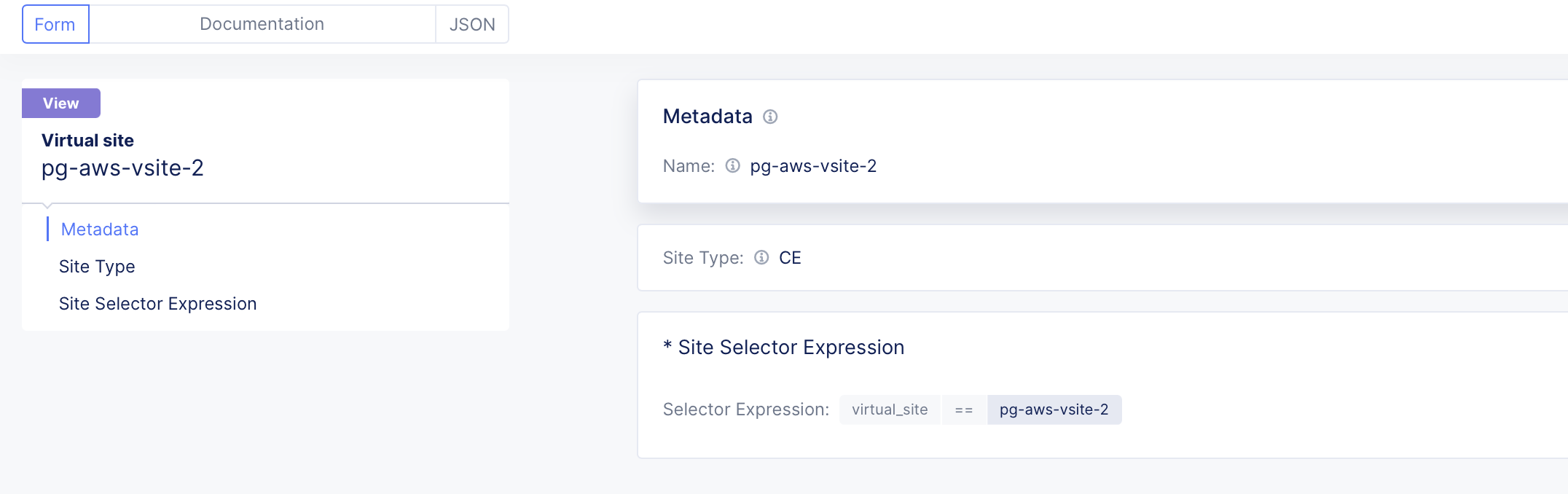
Figure: vSite Name
Assign CE Sites to Virtual Site
After the vSite is created, the CE sites created earlier are grouped using labels (with the Site selector expressions). As an example, the sites pg-aws-vsite-2a and pg-aws-vsite-2b are grouped together as a single vSite called pg-aws-vsite-2.
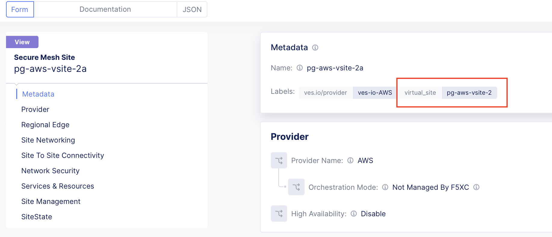
Figure: CE Site One
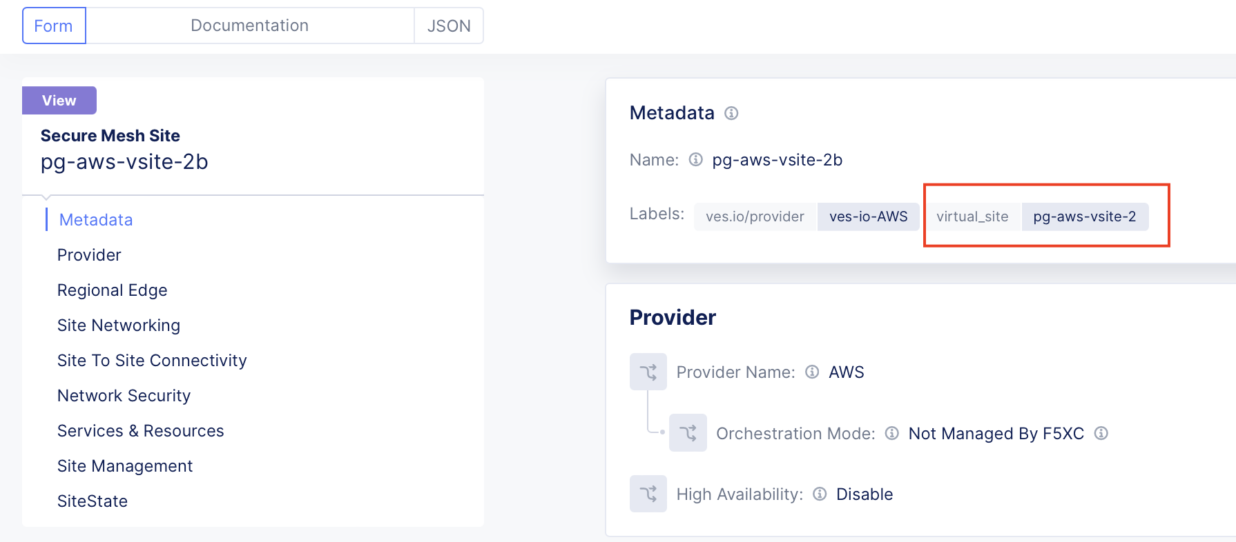
Figure: CE Site Two
Configure Origin Pool Using Virtual Site
To create an origin pool using a vSite, follow the steps provided.
Step 1: Create origin pool.
-
In Distributed Cloud Console, select Multi-Cloud App Connect.
-
Navigate to Manage > Load Balancers > Origin Pools.
-
Select Add Origin Pool.
Step 2: Configure origin pool.
-
Enter a name for the origin pool.
-
Select Add Item.
-
Use the virtual site option to select pg-aws-vsite-2.
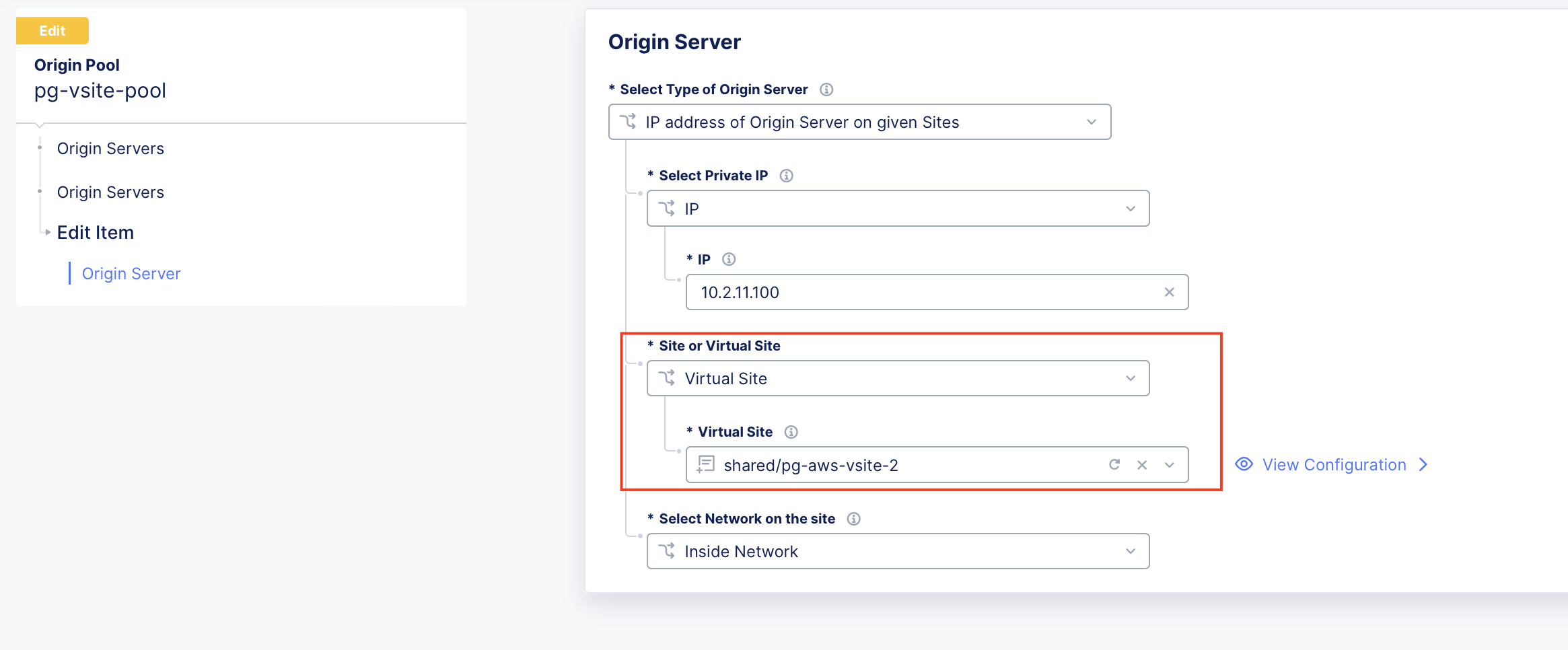
Figure: Origin Pool Configuration
-
Add the origin servers associated with the sites aggregated under pg-aws-vsite-2.
-
Select Apply.
Step 3: Save configuration.
- Ensure you create two origin servers. Both sites are in the same VPC/VNet or routed networks. Because of this, both CE sites have connectivity to each origin server in two different subnets (10.2.11.0/24 and 10.2.12.0/24).
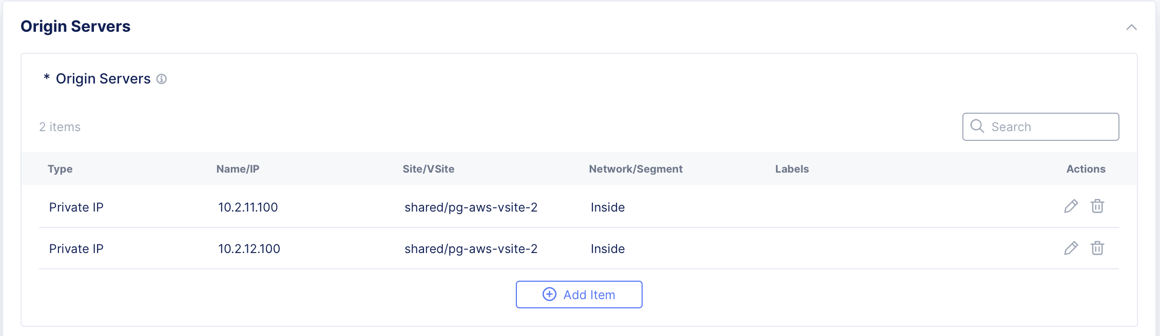
Figure: Two Subnets
- Configure a health check appropriate for the application origin pool.

Figure: Origin Pool Health Check
- Select Save and Exit.
Use Cases
Public Application Delivery Using Regional Edges
With this particular use case, the application is a public app, and therefore it is delivered to the public Internet using Regional Edges (REs) using F5’s global anycast network. The application itself is hosted in a customer location, like AWS, Azure, or on-premises, and is behind the virtual site (which is a group of two single-node CE sites). The communication between the Regional Edges (REs) and Customer Edges (CEs) is encrypted using either IPsec or SSL tunnels.
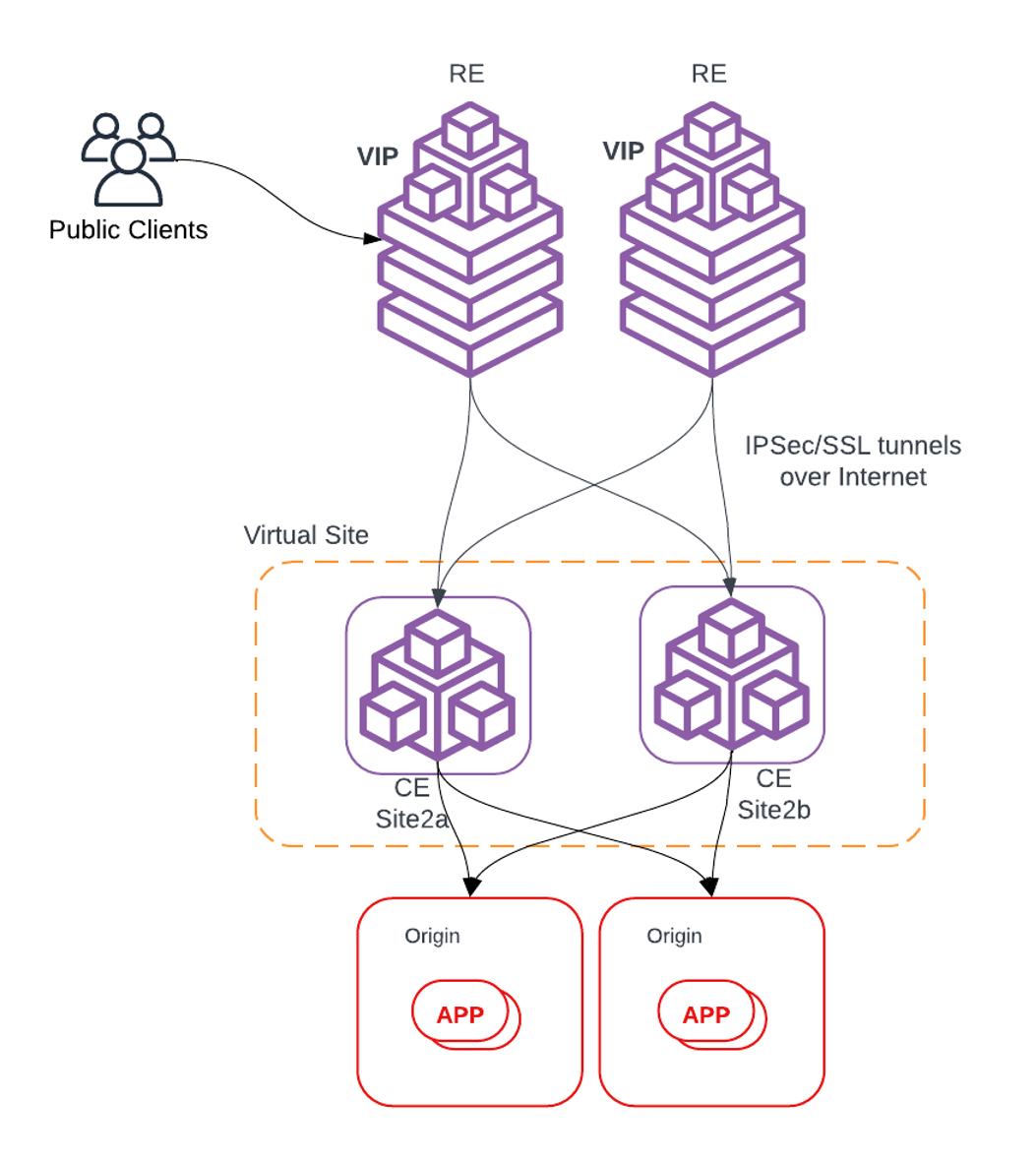
Figure: Public Application Delivery via RE
Configure Load Balancer
-
Configure a vSite. Refer to Configure Virtual Site for details.
-
Configure an origin pool using a vSite created in step 1. Refer to Configure Origin Pool Using vSite section using for details.
-
To advertise the application to the Regional Edges (REs):
- Navigate to the Multi-Cloud App Connect workspace.
- Select Manage > Load Balancers > HTTP Load Balancers.
- Select Add HTTP Load Balancer.
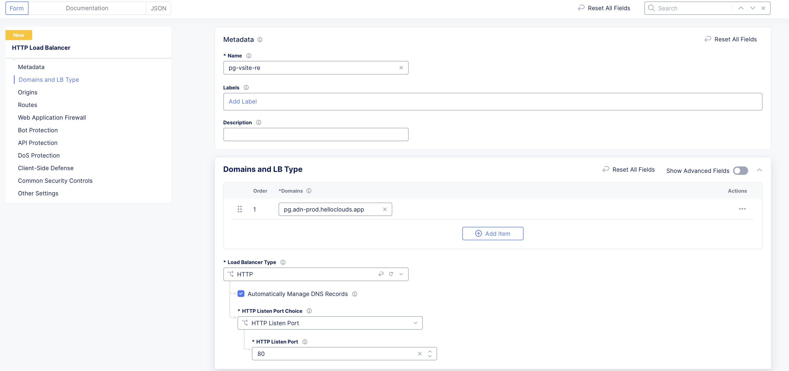
Figure: Configure Load Balancer
- Add the origin pool previously created.
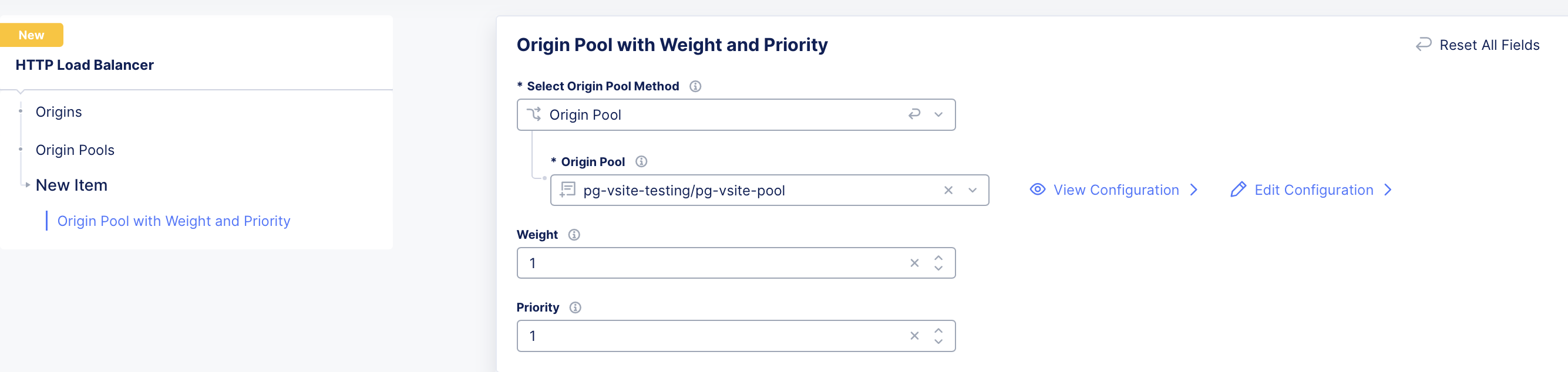
Figure: Configure Load Balancer
- From the VIP Advertisement menu, select Internet.
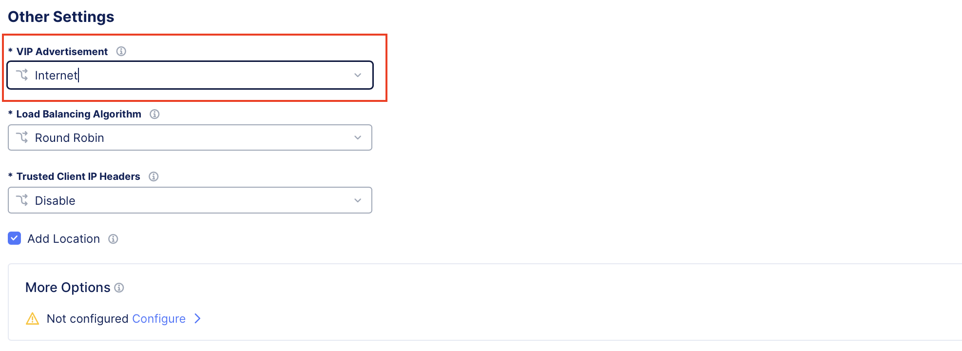
Figure: Configure Load Balancer
Note: As this application is delivered over the Internet, note that the REs manage the VIPs and that the origin servers are managed by sites grouped under vSite2.
Public Application Delivery Using Customer Edges Grouped as a Virtual Site
With this particular use case, the public applications are delivered to the Internet directly using Customer Edges (CEs) sites grouped as a single vSite. The origin pool is also behind the same CEs grouped as a vSite.
For public cloud providers, like AWS, Azure, and GCP, the cloud provider-specific network load balancer (NLB) is used for efficient load balancing of incoming traffic from the Internet to the CE sites. The NLB ensures high availability and scalability by routing traffic to the appropriate CE sites based on health checks and load distribution policies.
This configuration leverages the flexibility of F5 Distributed Cloud and an AWS/Azure/GCP NLB to provide robust traffic management, ensuring reliable access to services hosted on the CE sites.
Note: The procedure for AWS, Azure, and GCP is identical, with the only differences being in the configuration of the cloud provider's NLB.
In the diagram below, the App VIP is the cloud provider's NLB, and the LB for APP is the F5 Application Load Balancer. App Origin Pool are the applications in the same AWS/GCP VPC or Azure VNet as CEs.
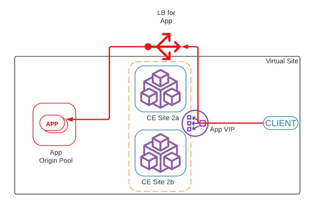
Figure: Public Application Delivery Using CEs as Single vSite
Configure Load Balancer
-
Configure a vSite. Refer to Configure Virtual Site for more information.
-
Configure an origin pool using a vSite created in step 1. Refer to Configure Origin Pool Using vSite section using for details.
-
Configure the F5 Distributed Cloud HTTP load balancer as described below:
- Navigate to the Multi-Cloud App Connect workspace.
- Select Manage > Load Balancers > HTTP Load Balancers.
- Select Add HTTP Load Balancer.
-
Configure the application domain and application origin pool created previously in Step 2.
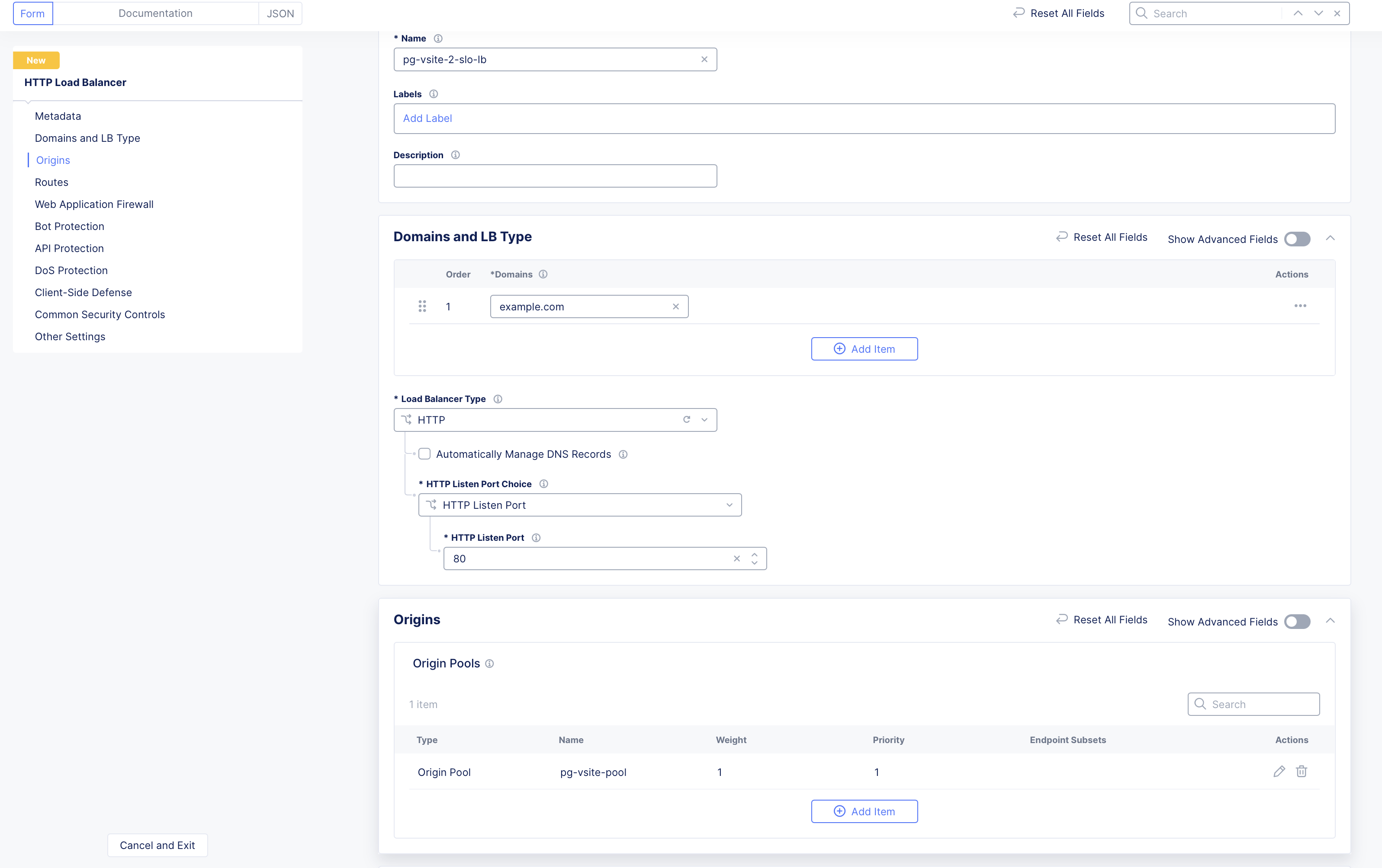
Figure: Configure Load Balancer
- From the VIP Advertisement menu, select the option to advertise the application on the Site Local Outside (SLO) of the vSite created in Step 1.
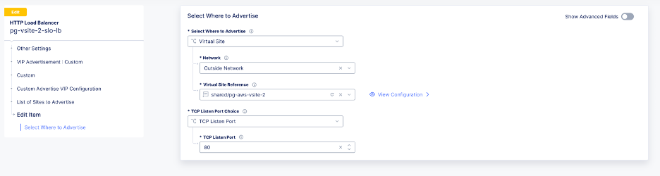
Figure: Configure Load Balancer
-
Create a cloud provider-specific NLB:
- For AWS, refer to Configure AWS Network Load Balancer for details
- For Azure, refer to Configure Azure Network Load Balancer for details.
- For GCP, refer to Configure GCP Network Load Balancer for details.
-
To reach the AWS NLB, you can use either the NLB VIP IP address or the AWS-provided domain name.
-
To reach the Azure or GCP NLB, you can use the NLB VIP IP address.
-
Ensure you expose the NLB VIPs to the Internet by assigning the Public IP address to the VIP.
Configure AWS Network Load Balancer
Create an AWS NLB using the steps in this section.
Step 1:
-
In AWS Console, navigate to the EC2 service.
-
Select Load balancers.
-
Select Create load balancer.
-
Choose Network Load Balancer and then select Create to proceed with the configuration.
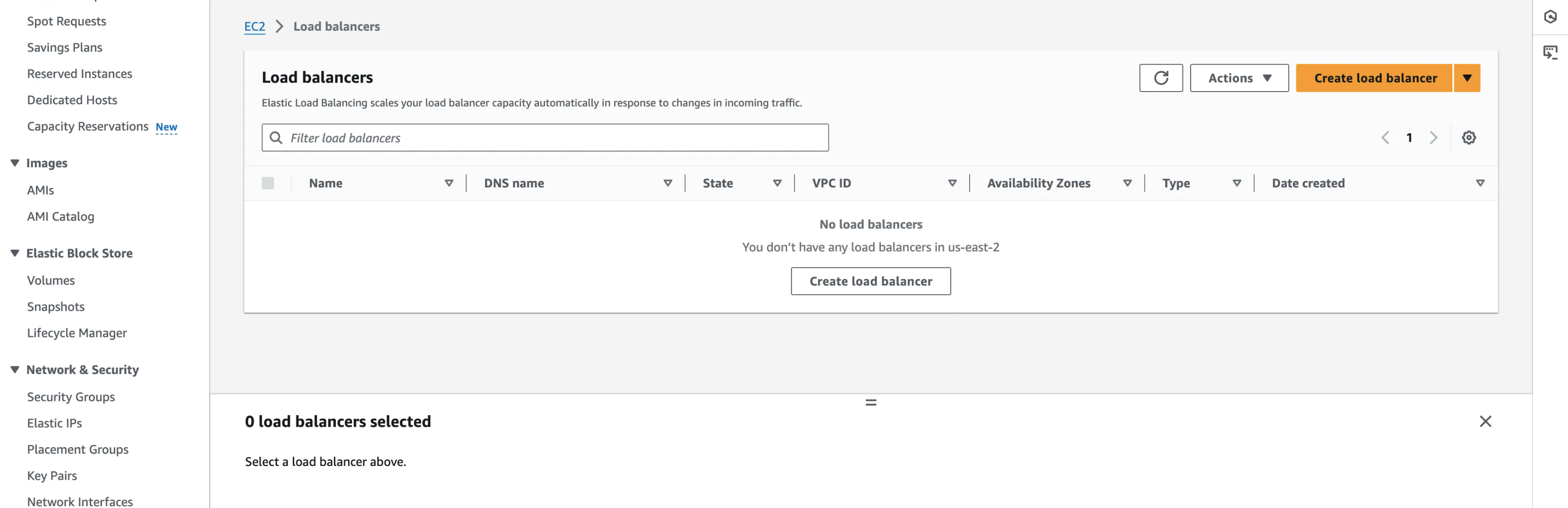
Figure: Configure AWS NLB
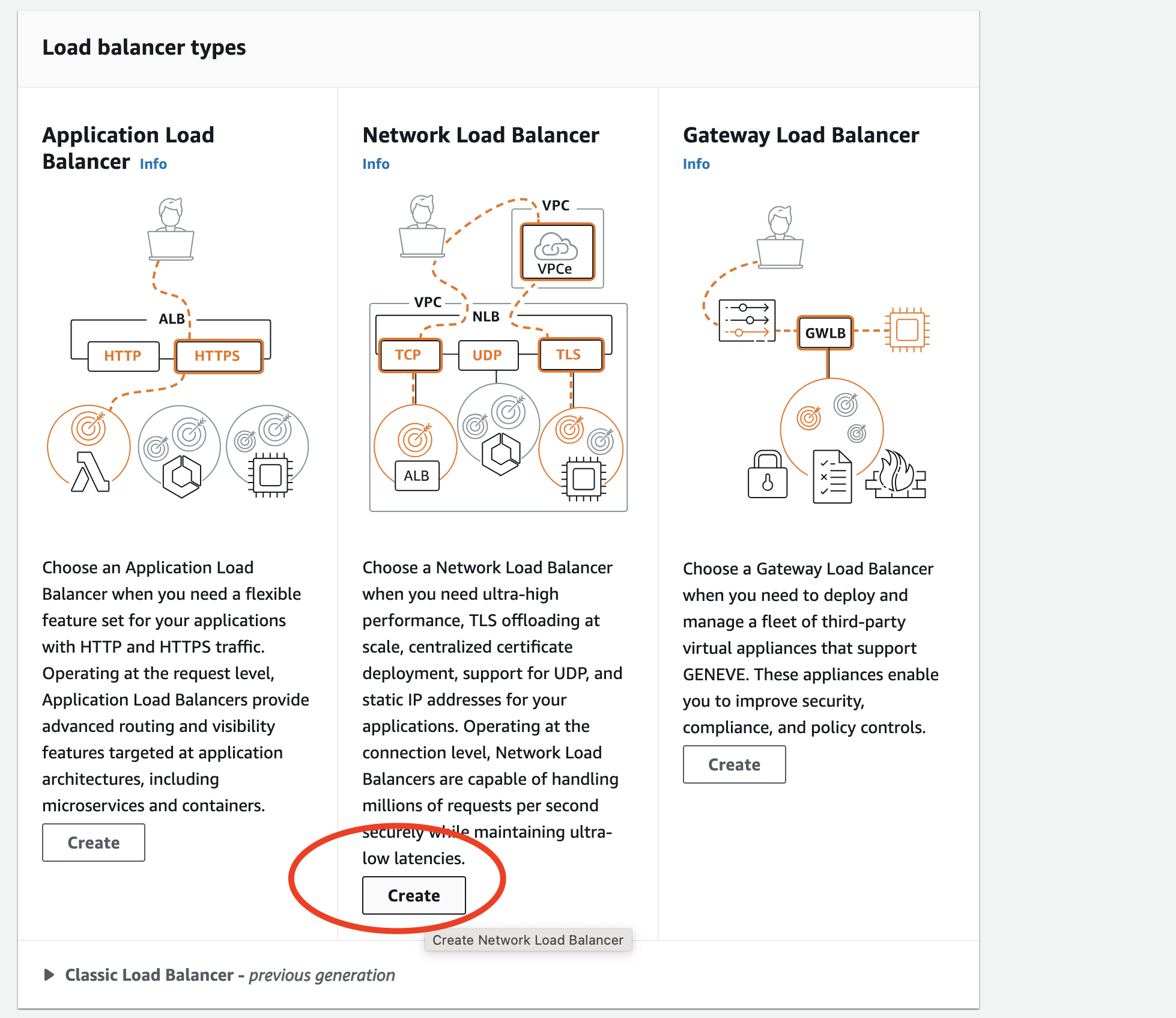
Figure: Choose AWS NLB
Step 2:
- Expose the AWS NLB VIP to the Internet (Internet-facing option).
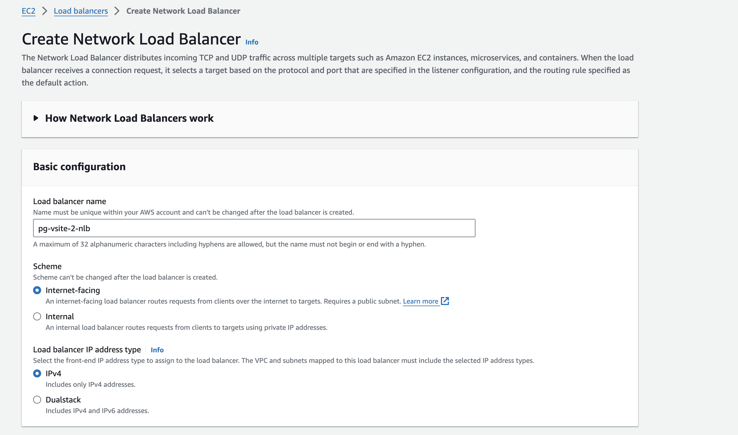
Figure: AWS NLB VIP Public
- Provide all the necessary information, like the VPC and subnets that contain the CE SLO interfaces.
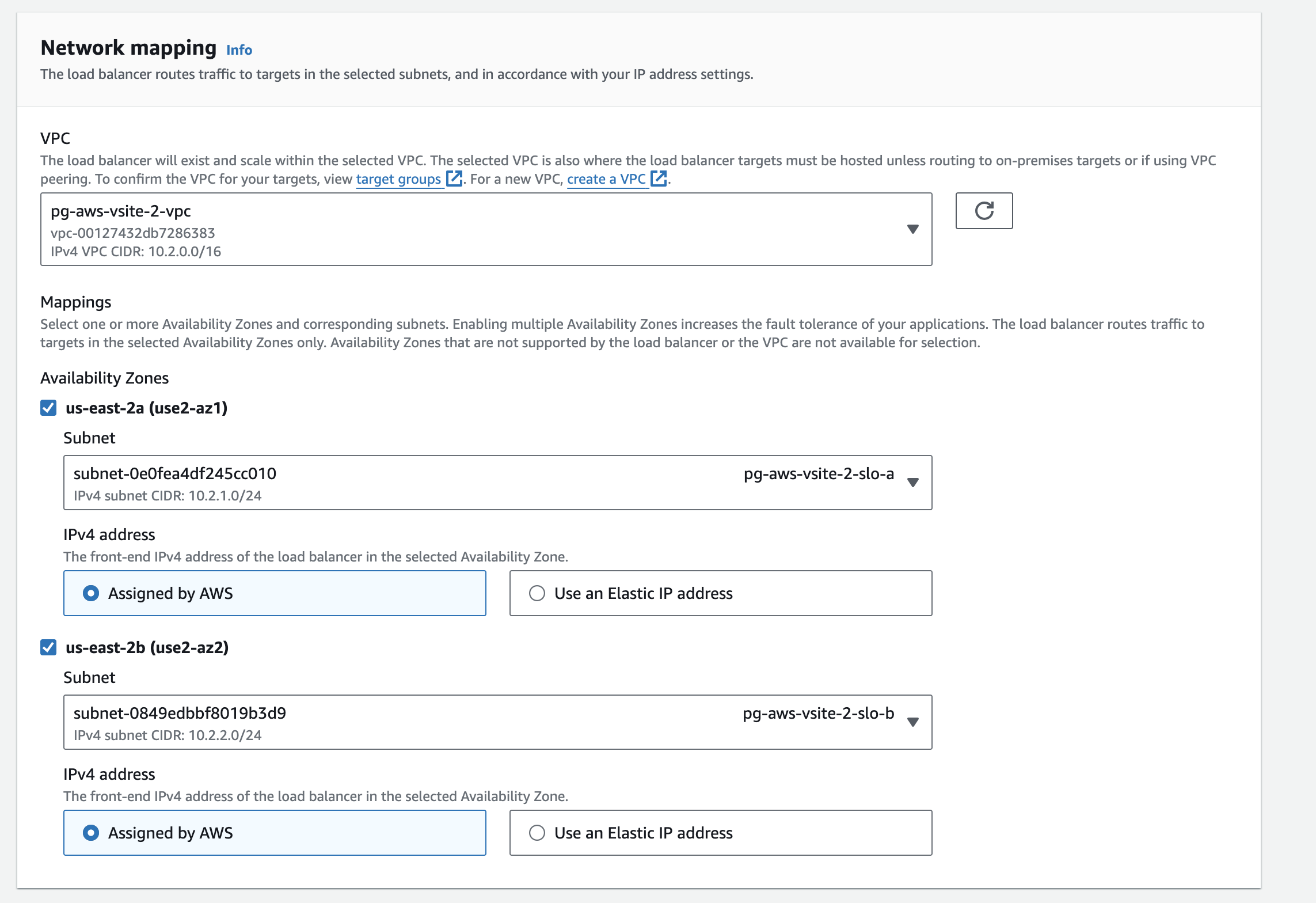
Figure: AWS NLB Network Mapping
- Define the security group and TCP listener port (TCP 80).
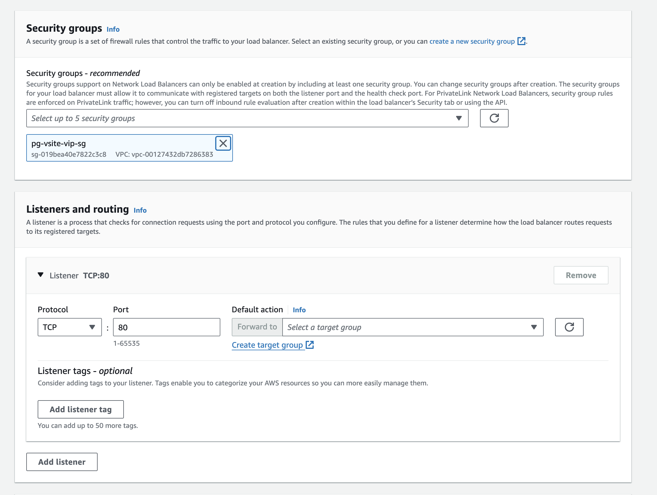
Figure: AWS NLB Security Group
Step 3:
- Define the target group that points to the F5 Distributed Cloud VIP IP addresses.
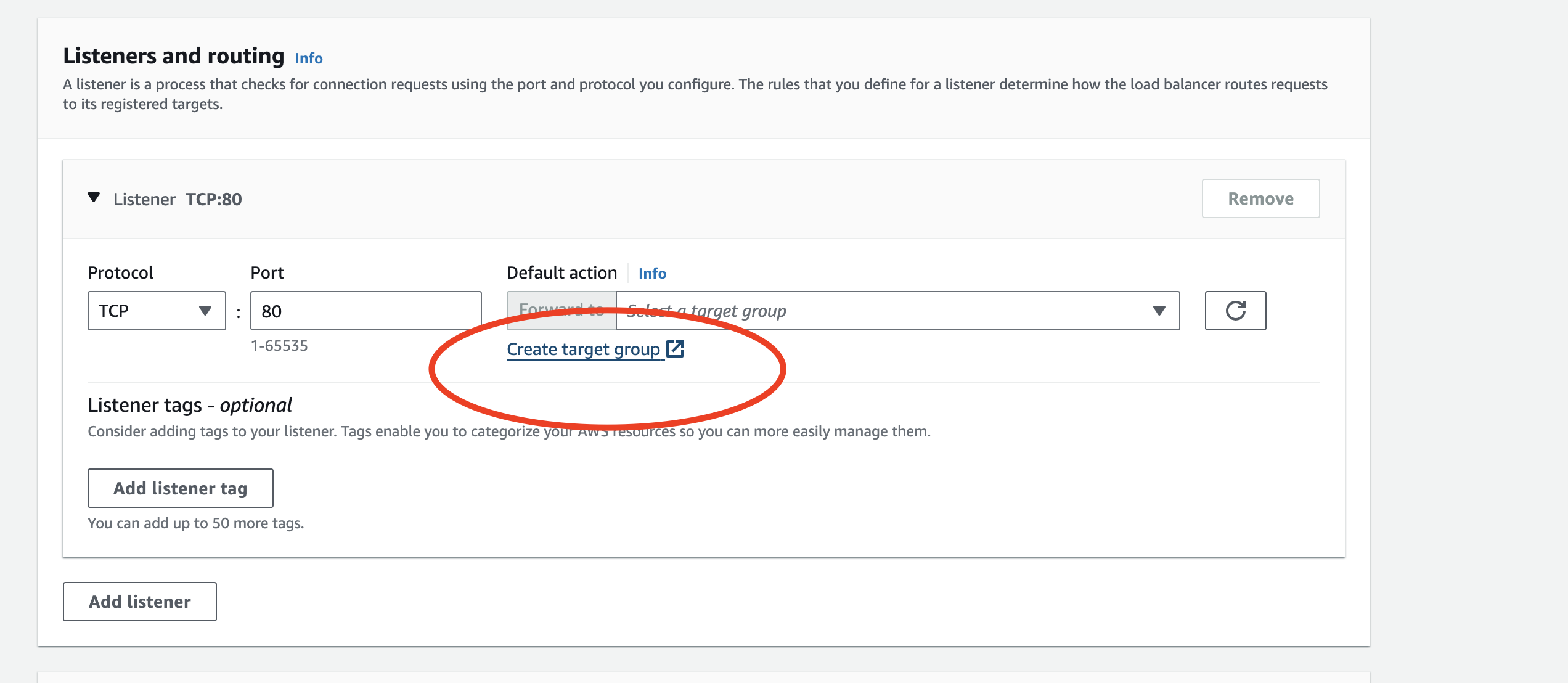
Figure: AWS NLB Target Group
- Choose an IP address-based target, as the F5 Distributed Cloud CE has multiple interfaces.
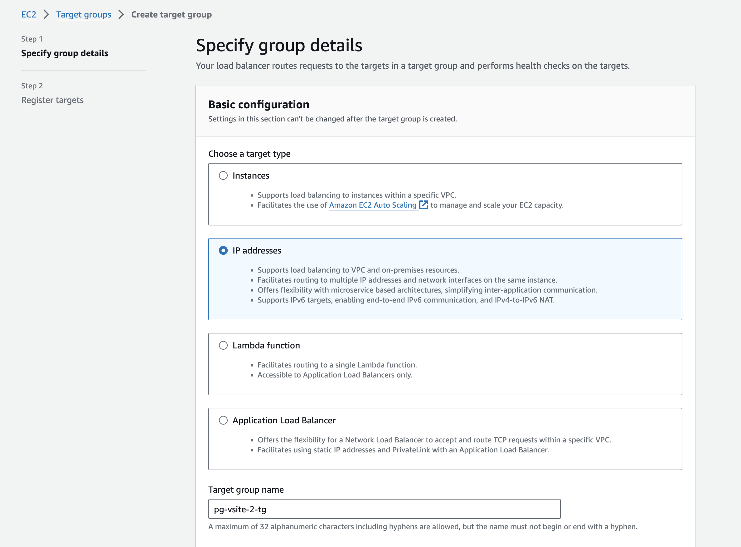
Figure: AWS NLB IP Address Target
- Define the target group port and health checks.
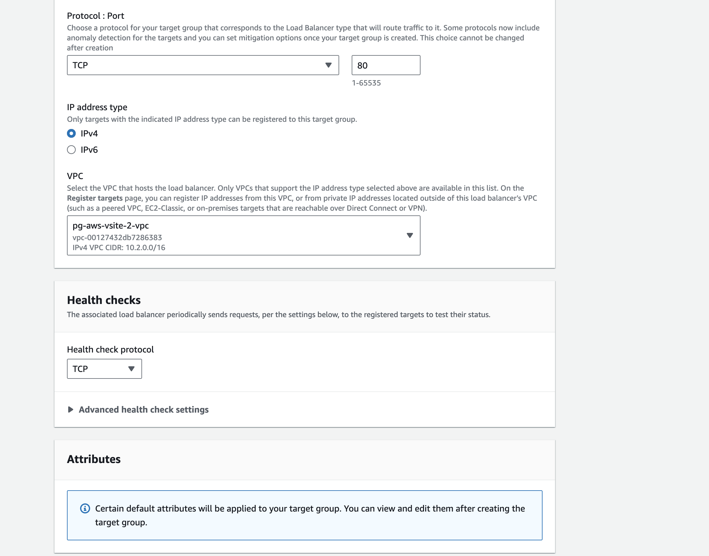
Figure: AWS NLB Health Check
Step 4:
- Locate the Site Local Outside (SLO) interface IP addresses for the CE sites. Follow these steps in F5 Console:
- In the Multi-Cloud Network Connect workspace, navigate to Overview > Infrastructure > Sites.
- For your CE sites, identify the SLO interfaces. Note the outside IP addresses for each CE.
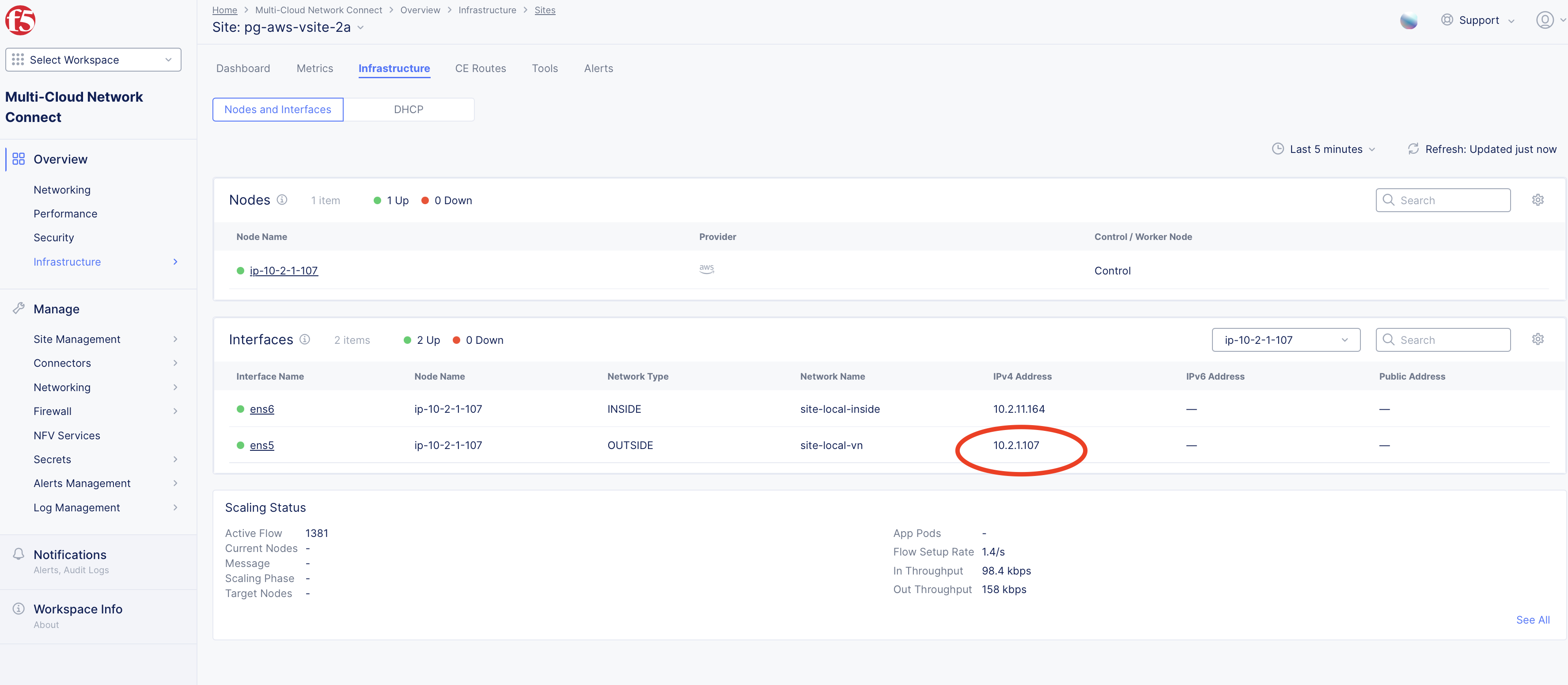
Figure: CE Site SLO Interface IP Address
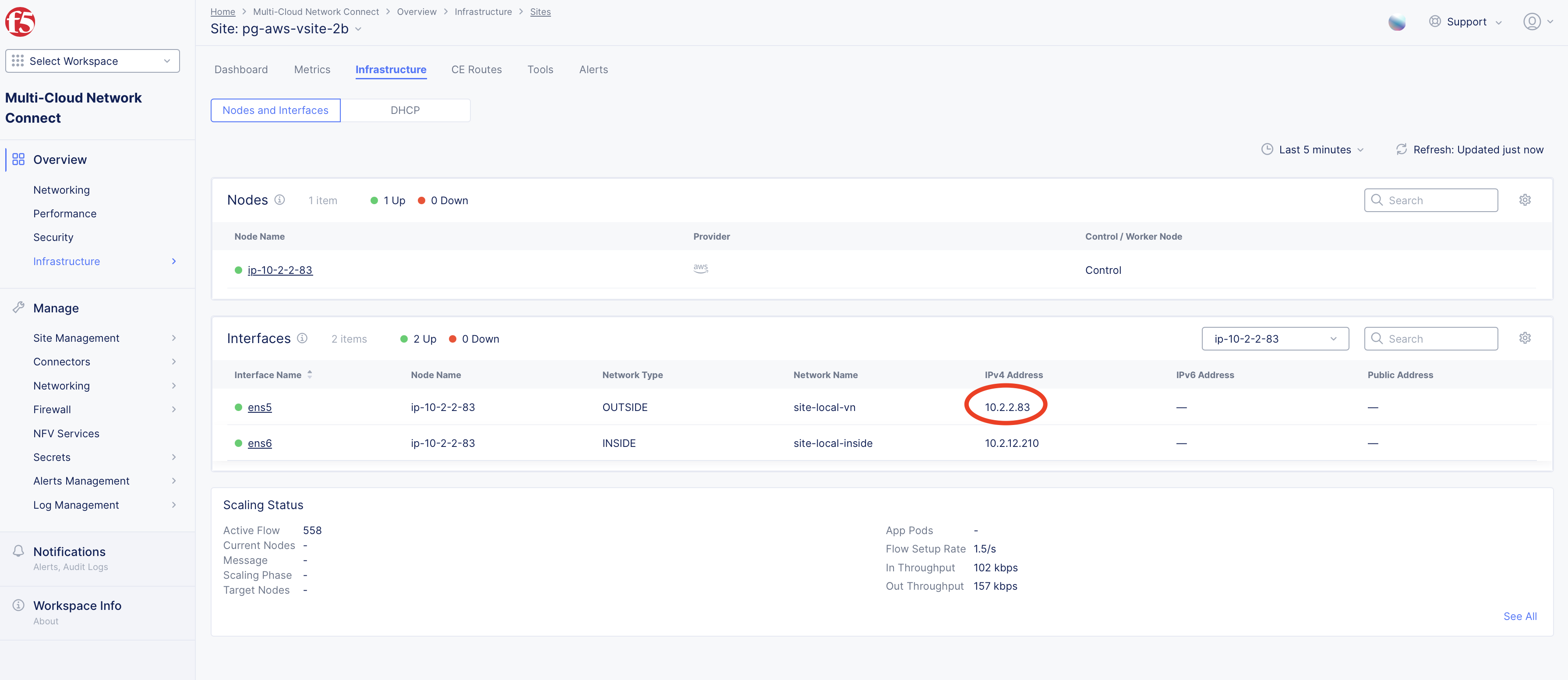
Figure: CE Site SLO Interface IP Address
- Specify the SLO IP addresses as targets.
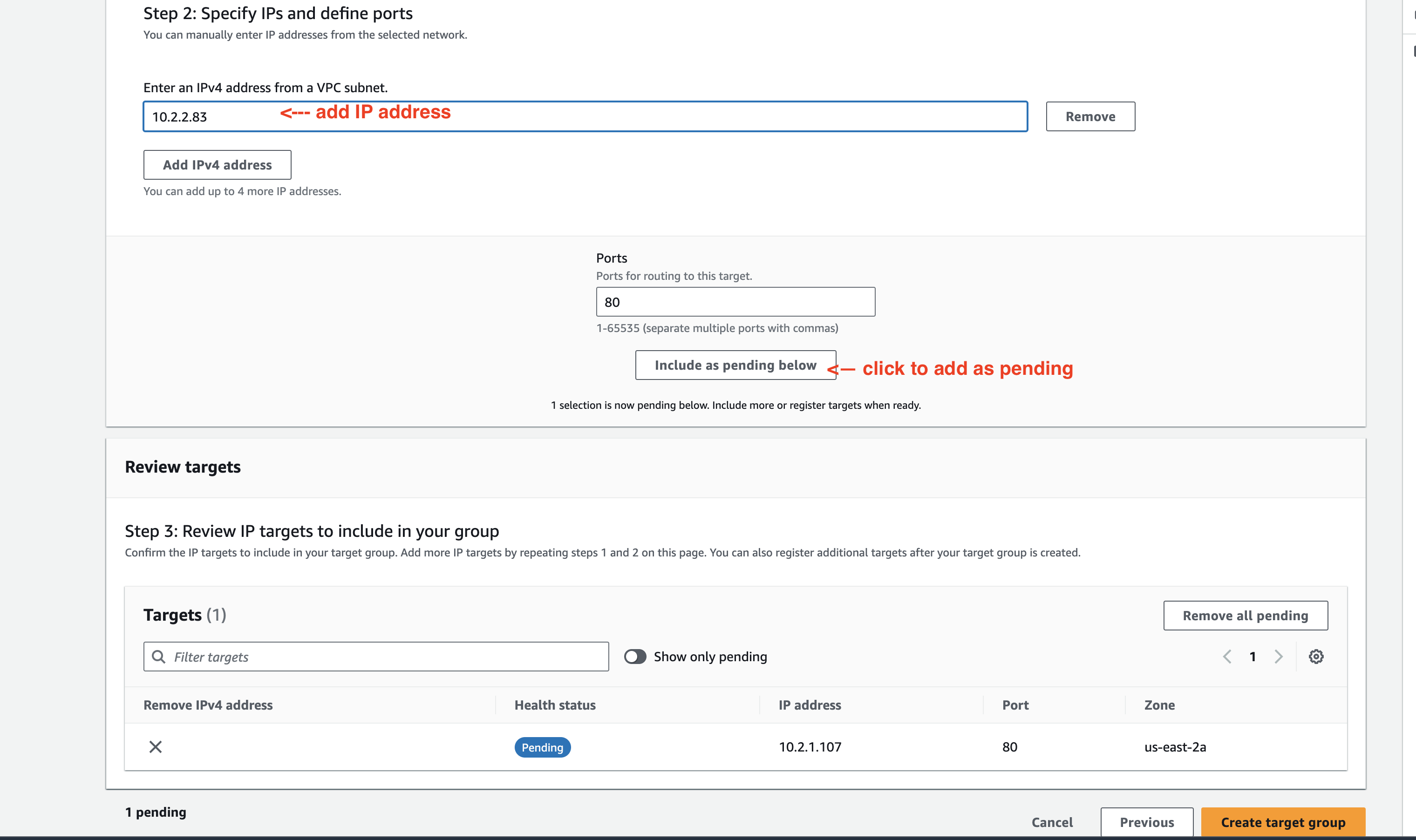
Figure: Specify SLO Interface IP Addresses
-
After you add both IP addresses, select Create target group.
-
Verify the IP addresses under Registered targets section.
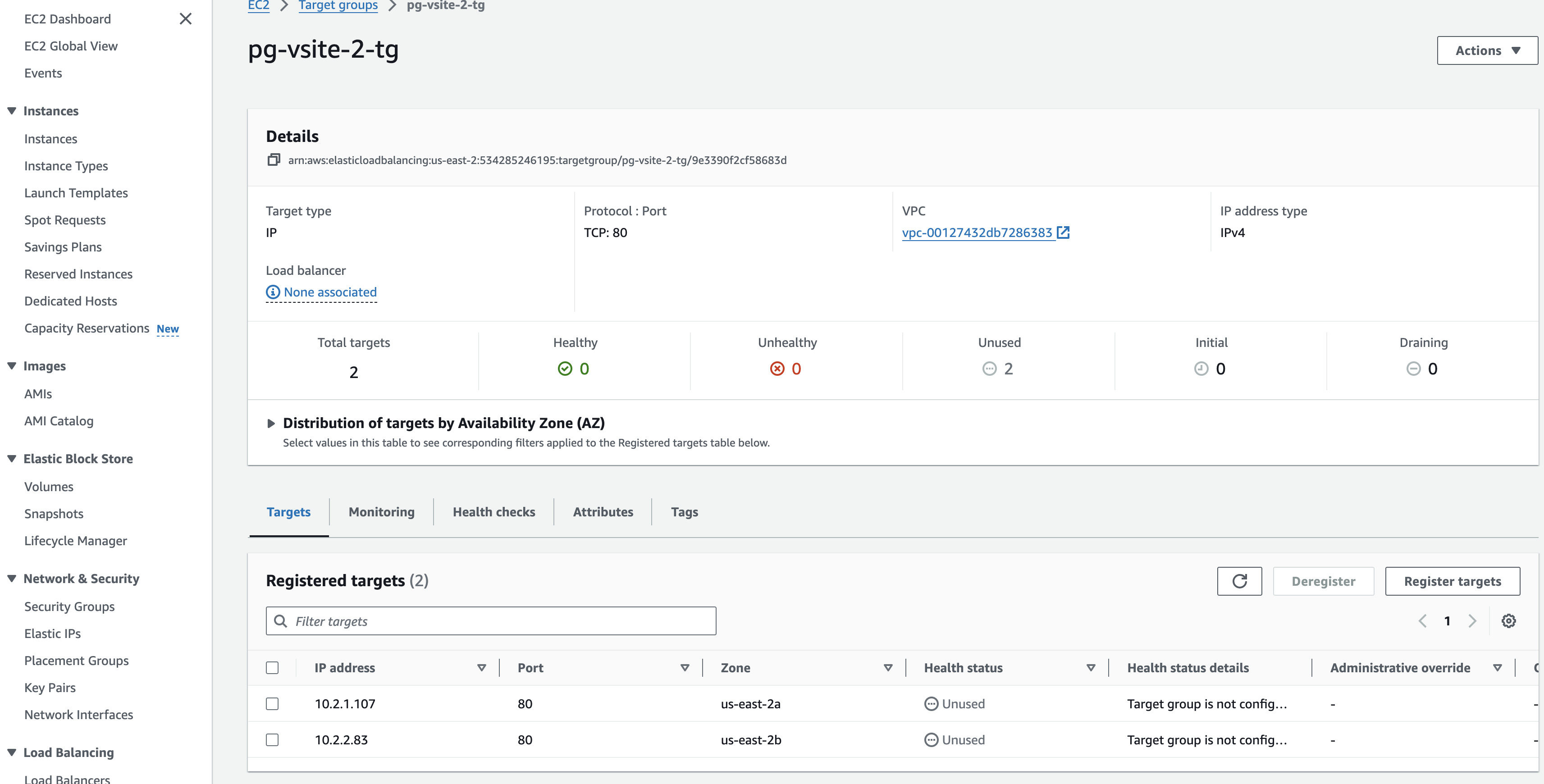
Figure: Verify SLO Interface IP Addresses
- In the AWS Network Load Balancer window, select Refresh Target groups and choose the previously created target group.
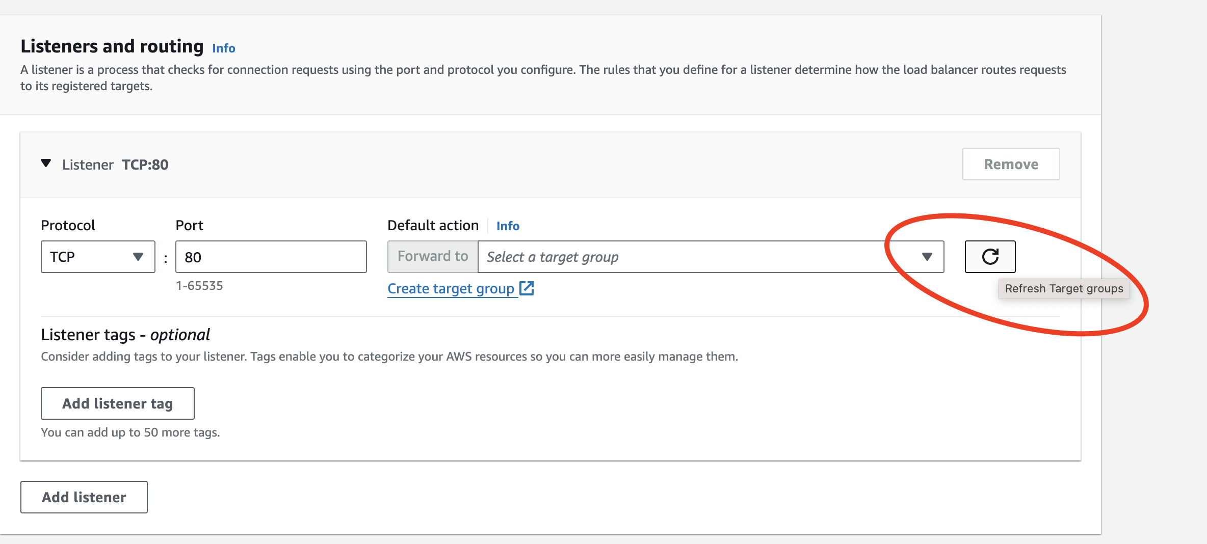
Figure: Refresh Target Groups
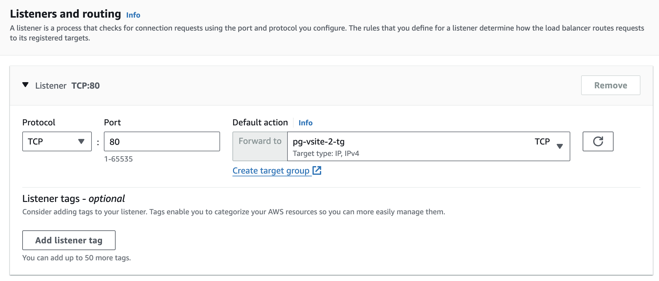
Figure: Add Target Group
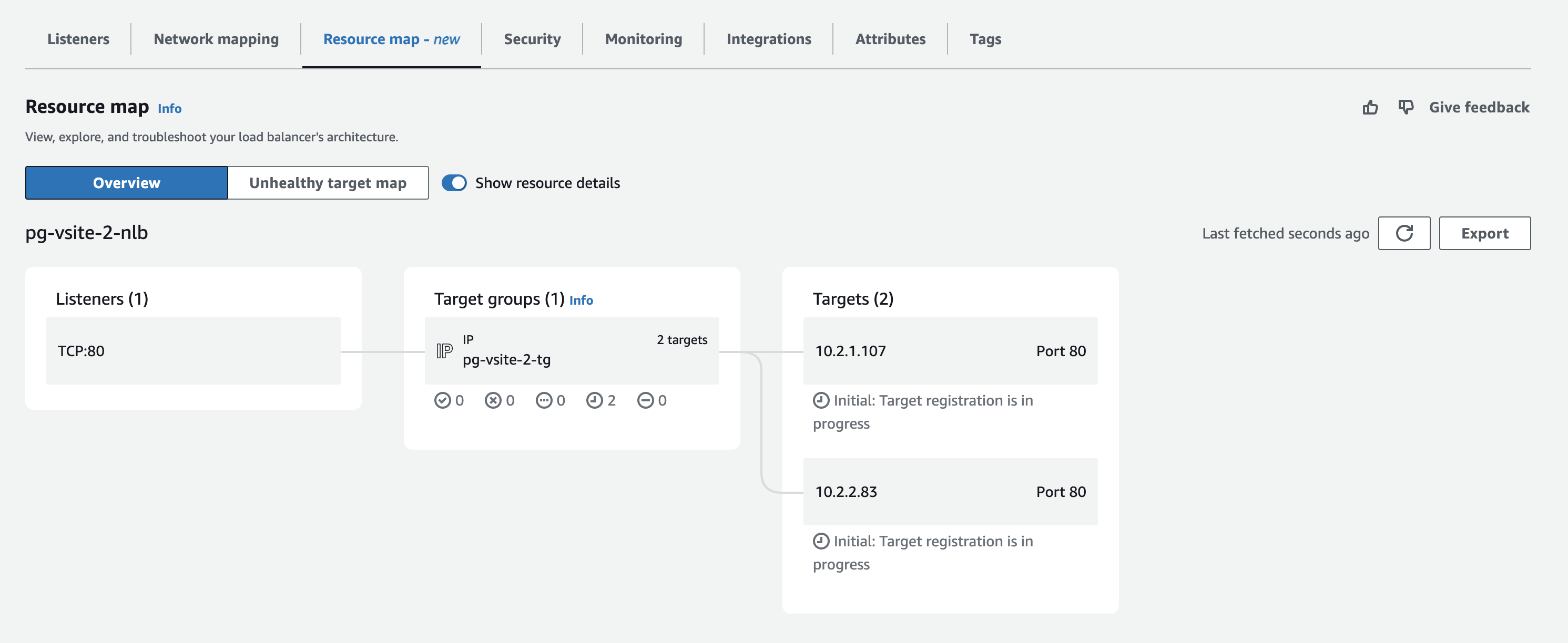
Figure: Resource Map View
Step 5:
-
Enable cross-zone load balancing to distribute traffic across availability zones:
- In the NLB settings, select on Enable cross-zone load balancing.
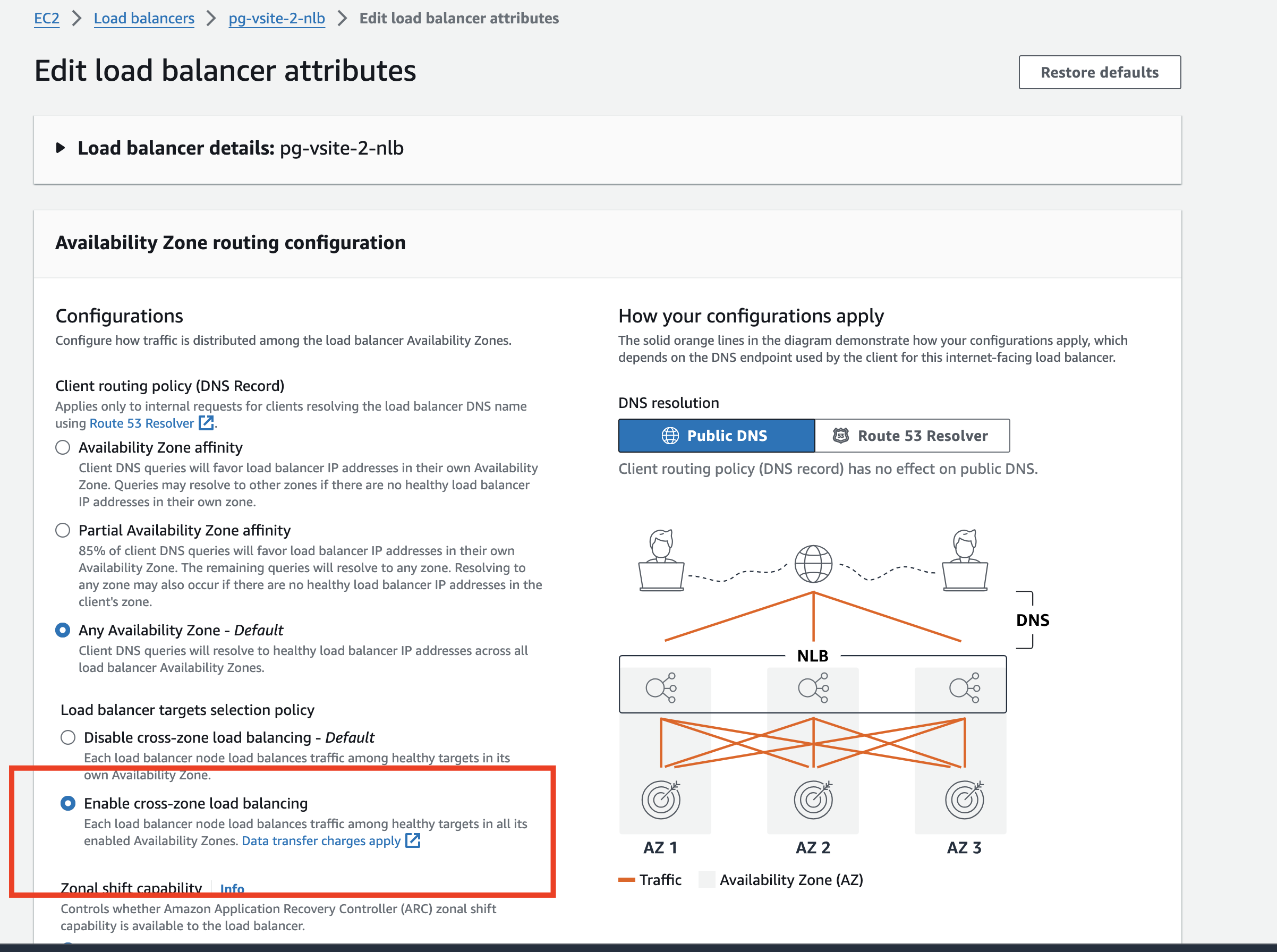
Figure: Enable CZLB
- As a good practice, enable health checks to validate per CE site VIP reachability by AWS NLB.

Figure: Enable Health Check
Configure Azure Network Load Balancer
Create an Azure NLB using the steps in this section. Note that to advertise apps to the Internet directly using CEs, an Azure NLB with a public IP address is required in front of the CE.
Step 1:
-
In your Resource Group, create a new resource of type NLB.
-
Ensure that the Type is set to Public.
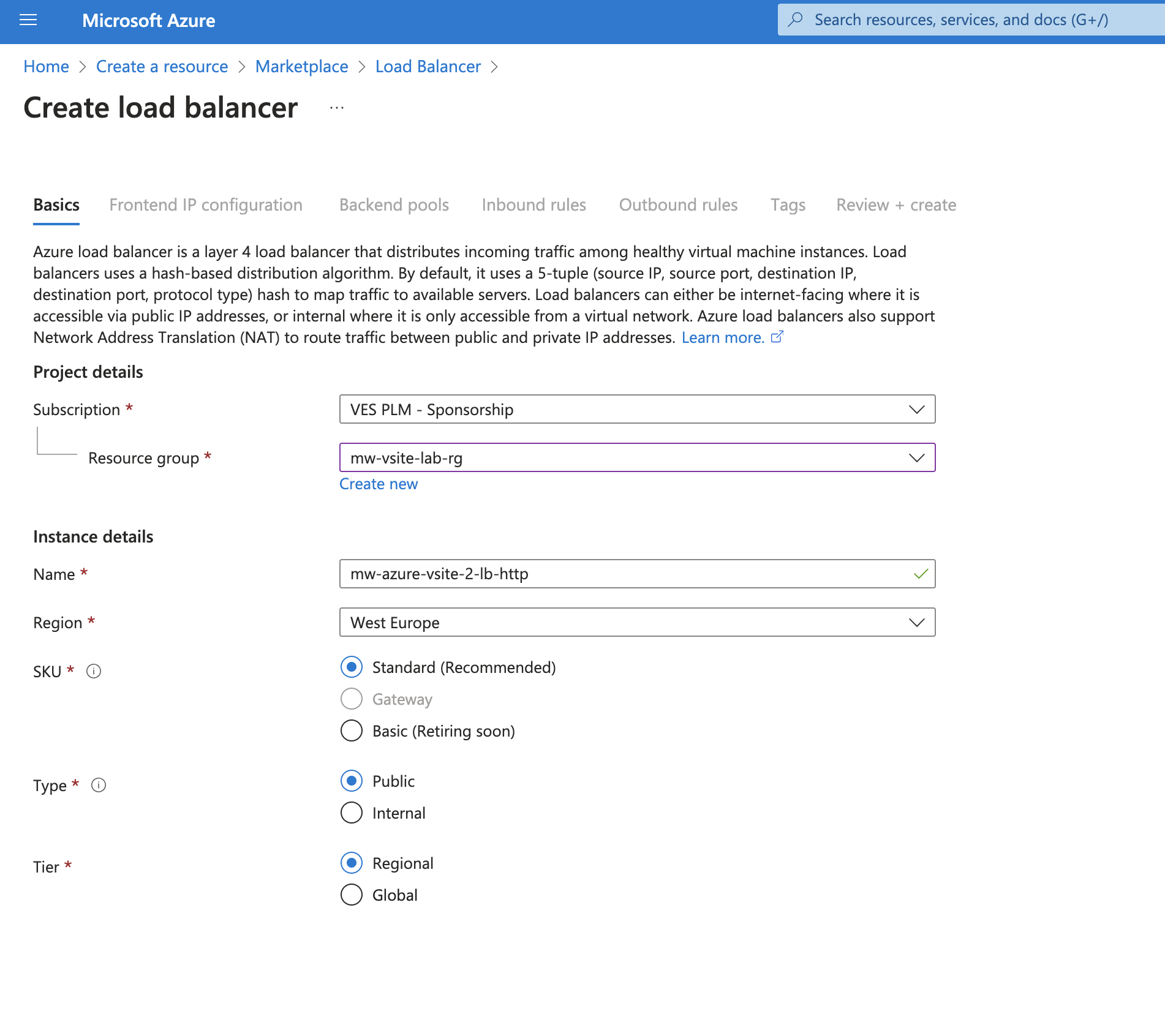
Figure: Set NLB Type
Step 2:
- To assign the Public IP to Frontend IP, use one of the existing public IP addresses previously created. If you do not have one, create it using resource Public IP addresses.
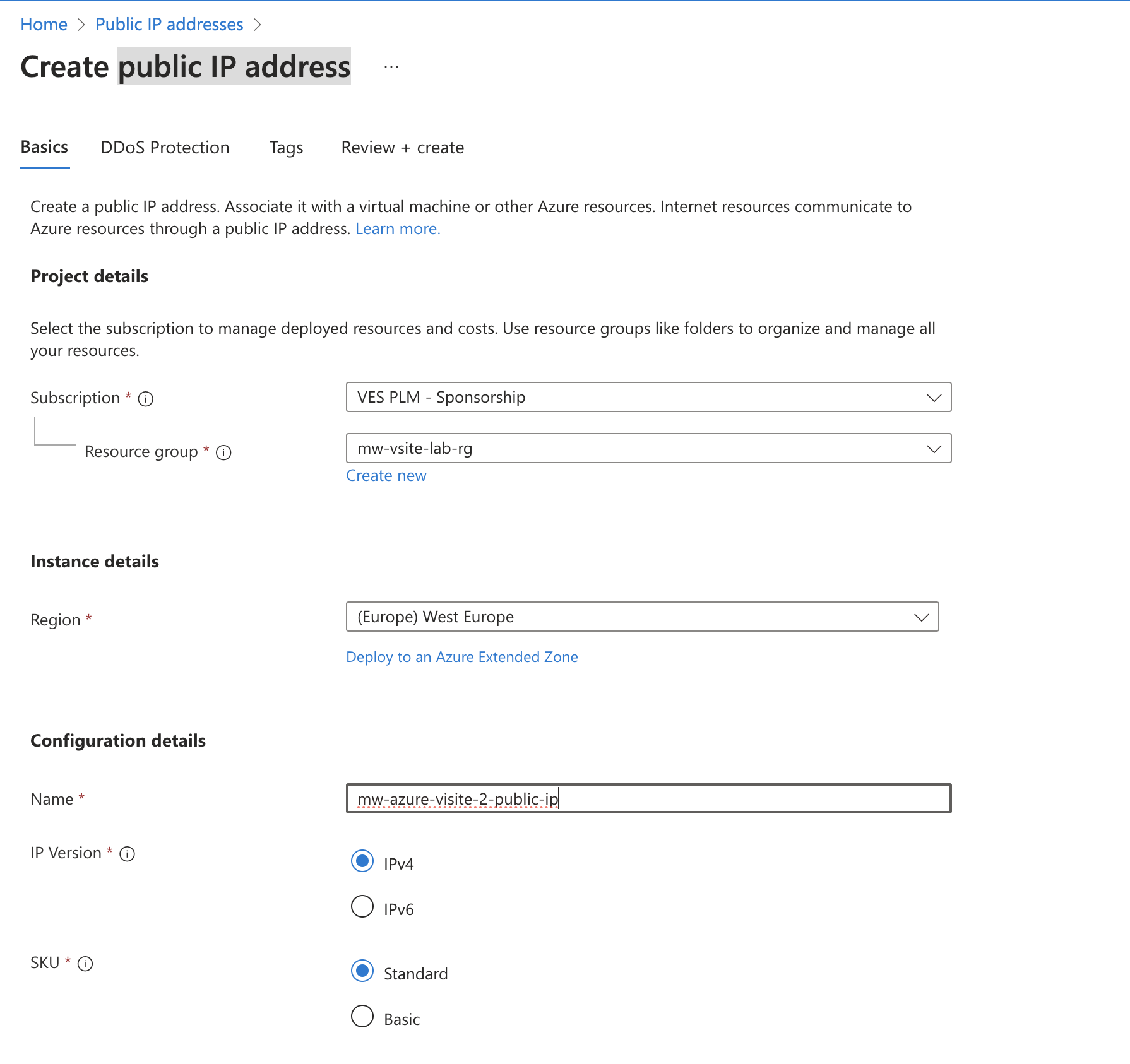
Figure: Create Public IP Address
- After the public IP address is ready, add it as the frontend IP address.
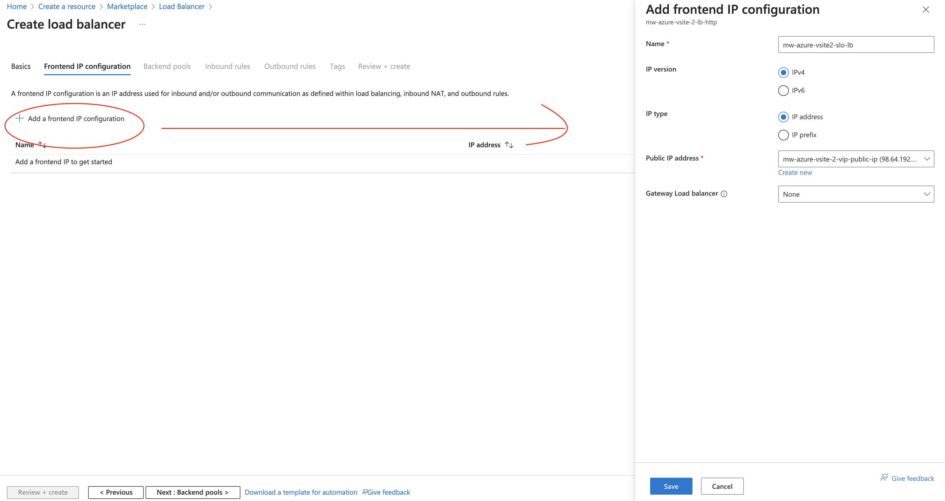
Figure: Add Frontend IP Address
- For the backend pool, choose the SLO interfaces as pool members selected by NIC.
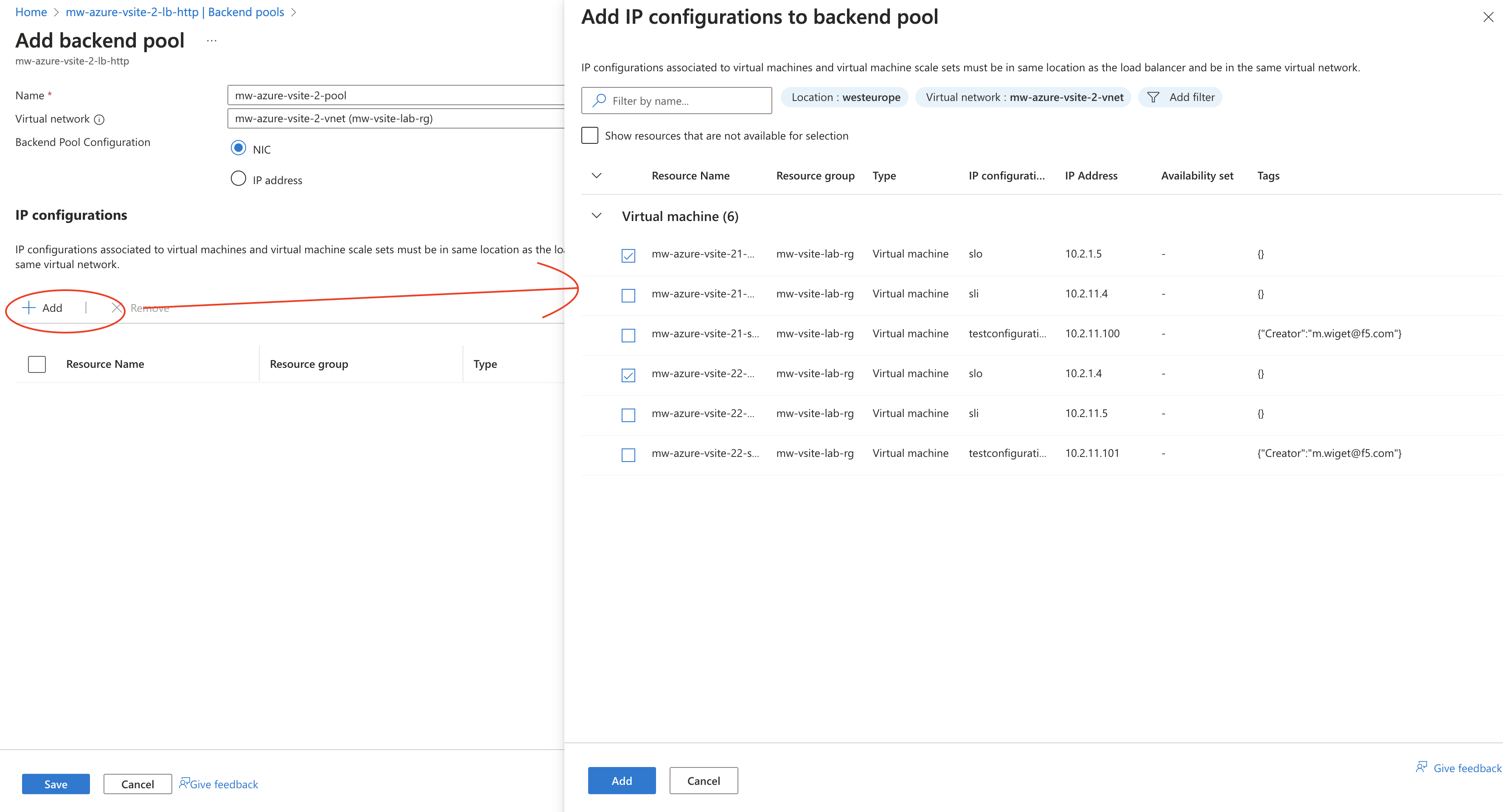
Figure: Add SLO Interfaces
Step 3:
- Add load balancing rules.
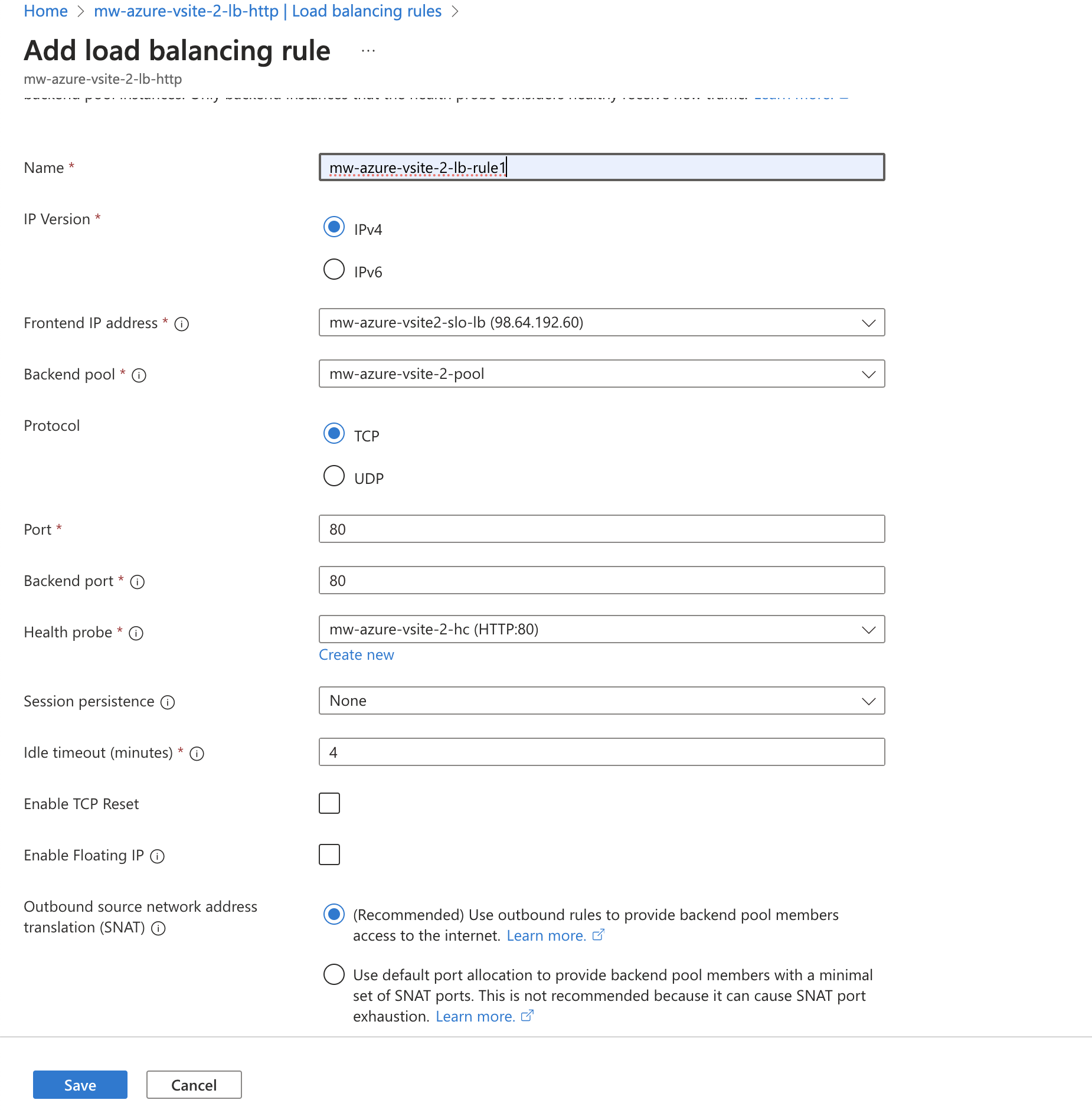
Figure: Add Load Balancer Rules
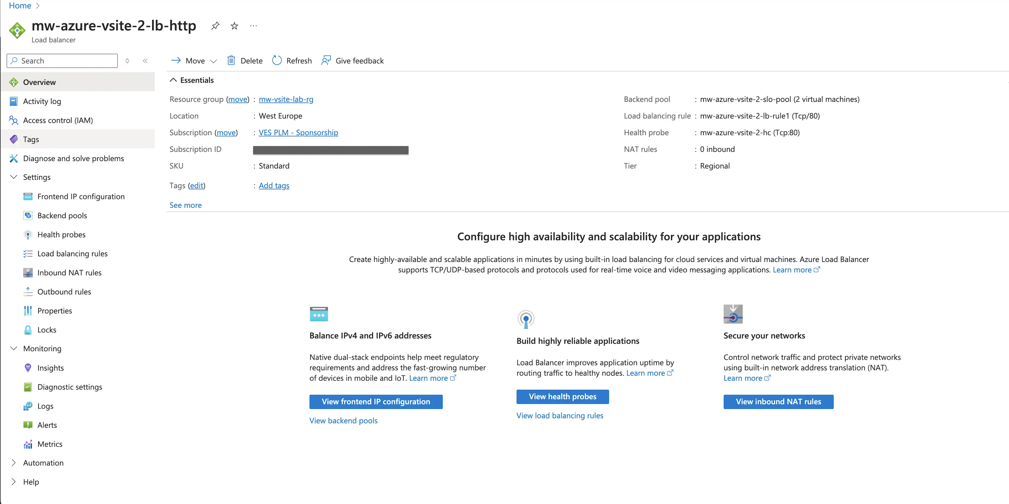
Figure: Load Balancer Rule Summary
- Optionally, add health probes to actively monitor the health of Distributed Cloud VIP addresses.
Configure GCP Network Load Balancer
Create a GCP NLB using the steps in this section. The NLB targets the outside interfaces of the CE sites.
Step 1: Create network endpoint groups.
-
In GCP Console, navigate to Compute Engine > Settings > Network endpoint groups.
-
Select Create network endpoint group and configure as below for CE Site 1:
- Provide the name.
- From the Network endpoint group type menu, select Zonal NEG.
- Select the Endpoint types as GCE_VM_IP.
- In Network, select the VPC where the CEs are deployed.
- In Subnetwork, select the SLO subnet.
- In Zone, select the zone where the CE Site 1 is deployed.
- Select Create.
-
Select on the newly created network endpoint group, and then select Add network endpoint.
-
Select the VM instance for CE Site 1 and then select Create.
-
Repeat the steps above to create another network endpoint group for CE Site 2.
Step 2: Create NLB.
-
In GCP Console, navigate to Networking > Network services > Load balancing.
-
Select Create load balancer.
-
Select Type of load balancer as Network load balancer. Select Next.
-
For the Proxy or passthrough option, select Passthrough load balancer. Select Next.
-
For the Public facing or internal option, select Public facing (external). Select Next.
-
On the Create load balancer step, select Configure.
-
On the NLB create wizard that opens, configure the following properties:
- Provide the load balancer name.
- Select the region where the CEs are deployed.
-
For the Backend configuration, provide the following properties:
- Backend type: Zonal network endpoint group
- Protocol: TCP
- Backends: Add new backends and select the network endpoint groups created in the previous step.
- Health check: Create a new health check for TCP port 80.
-
For the Frontend configuration, provide the following properties:
- Provide a name for the VIP.
- IP version: IPv4
- Network Service Tier: Standard
- IP address: Reserve a new external static IP address.
- Ports: Multiple
- Port numbers: 80,443
- Review the configurations and then select Create.
Public Application Delivery Across Customer Edges Grouped into a Virtual Site
In this particular use case, the application is private and is delivered to other Customer Edge (CE) sites grouped into a vSite. In this example, the application is advertised to Customer Edges (CEs) grouped by vSite-1 and the application origin pool is behind Customer Edge (CE) sites grouped by vSite-2. To balance traffic to CE VIPs on vSite-1, an AWS, Azure, or GCP NLB is used. The CE sites in the two vSites can be connected directly using Site Mesh Group, DC Cluster Group, or over Regional Edges (REs).
The procedure for AWS and Azure is identical, with the only difference being the configuration of the cloud provider's NLB.
In the diagram below, the App VIP is the AWS, Azure, or GCP NLB, and the LB for APP is the F5 Application Load Balancer. App Origin Pool are the applications in the same AWS VPC or Azure VNet as CEs in vSite-2 origin.
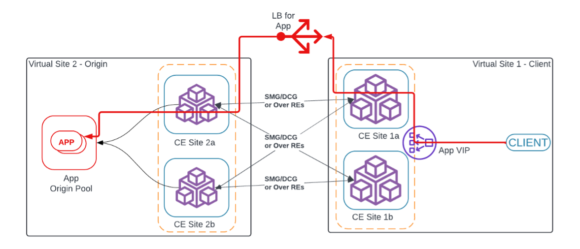
Figure: Public Application Delivery Across CEs Grouped into Single vSite
Configure Load Balancer
- Configure vSite. Refer to Configure Virtual Site for more information. In this example, two vSites are created: pg-aws-vsite-1 for client and pg-aws-vsite-2 for origin pool. The sites pg-aws-vsite-1a and pg-aws-vsite-1b are grouped into virtual site pg-aws-vsite-1. The sites pg-aws-vsite-2a and pg-aws-vsite-2b are grouped into virtual site pg-aws-vsite-2.
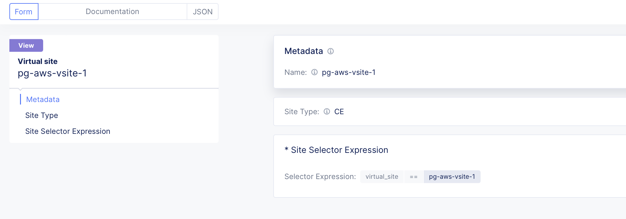
Figure: pg-aws-vsite-1 for Client

Figure: pg-aws-vsite-2 for Origin Servers
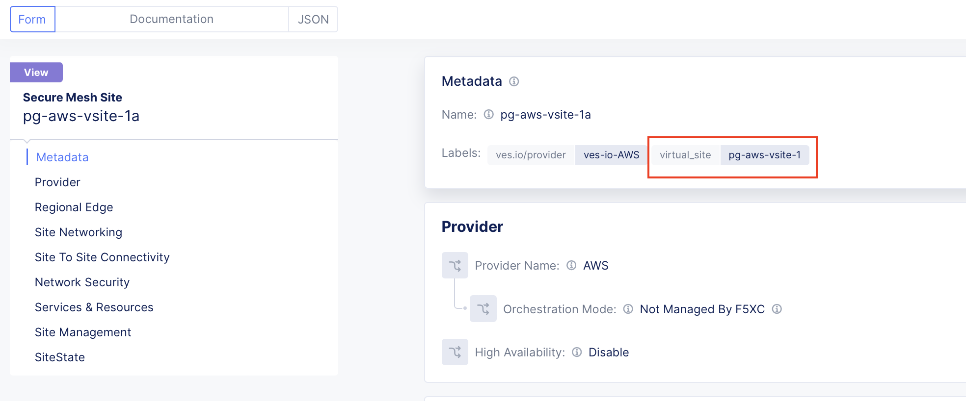
Figure: Site pg-aws-vsite-1a - label pg-aws-vsite-1
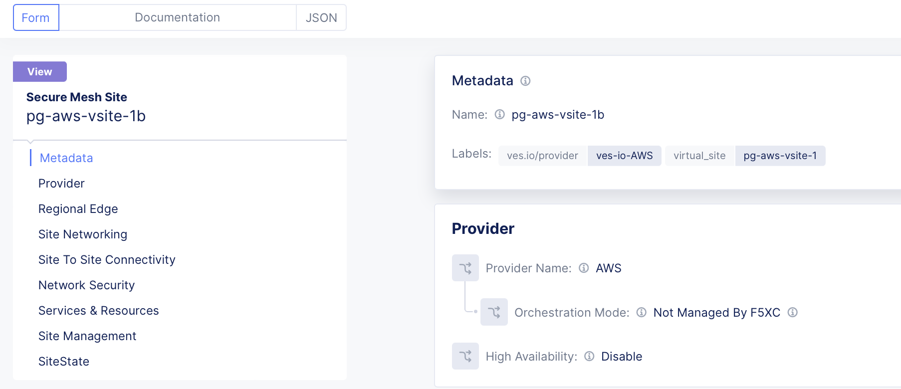
Figure: Site pg-aws-vsite-1b - label pg-aws-vsite-1
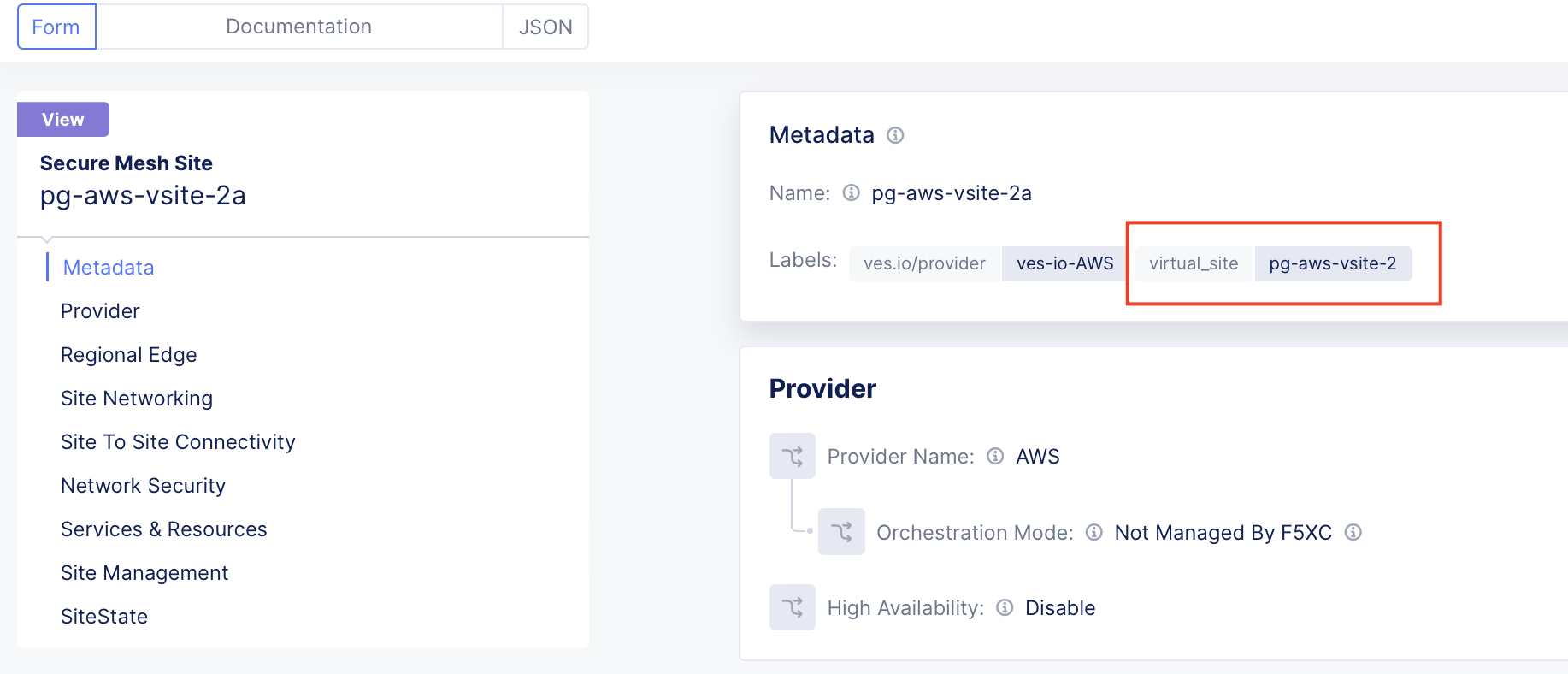
Figure: Site pg-aws-vsite-2a - label pg-aws-vsite-2
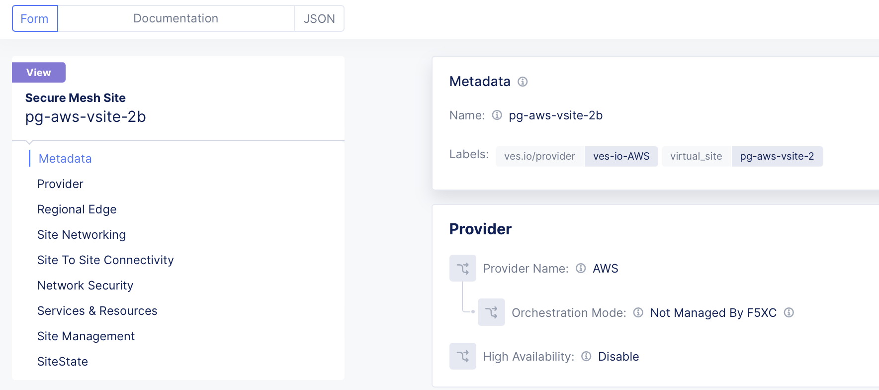
Figure: Site pg-aws-vsite-2b - label pg-aws-vsite-2
-
Configure an origin pool using the virtual site pg-aws-vsite-2 created in Step 1. Refer to Configure Origin Pool Using vSite section using for more information.
-
To advertise the application to CEs:
- Navigate to the Multi-Cloud App Connect workspace.
- Select Manage > Load Balancers > HTTP Load Balancers.
- Select Add HTTP Load Balancer.
- In the Origins section, select the origin pool previously created.
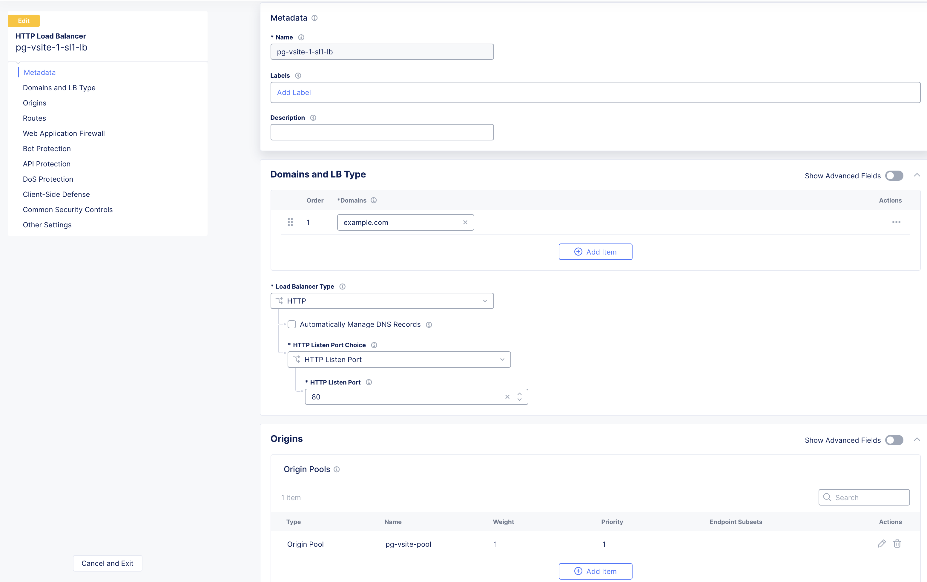
Figure: Select Origin Pool
- From the VIP Advertisement menu, select the option to advertise the application on the Site Local Inside (SLI) of the Virtual Site pg-aws-vsite-1 previously created in Step 1.
Note: Each CE Site has a VIP configured on its SLI interface IP address, which acts as the backend (origin pool) for the external load balancer. In this case, an AWS, Azure, or GCP NLB.
-
Create a cloud provider-specific NLB:
- For AWS, refer to Configure AWS Network Load Balancer for details
- For Azure, refer to Configure Azure Network Load Balancer for details.
- For GCP, refer to Configure GCP Network Load Balancer for details.
-
To reach the AWS NLB, you can use either the NLB VIP IP address or the AWS-provided domain name.
-
To reach the Azure or GCP NLB, you can use the NLB VIP IP address.
-
Ensure you expose the AWS, Azure, or GCP VIPs to the Internet by assigning the Public IP address to the VIP.
Configure AWS Network Load Balancer
Create an AWS NLB using the steps in this section.
Step 1:
-
In AWS Console, navigate to the EC2 service.
-
Select Load balancers.
-
Select Create load balancer.
-
Choose Network Load Balancer and then select Create to proceed with the configuration.
Figure: Configure AWS NLB
Figure: Choose AWS NLB
Step 2:
- Expose the AWS NLB VIP internally (Internal option).
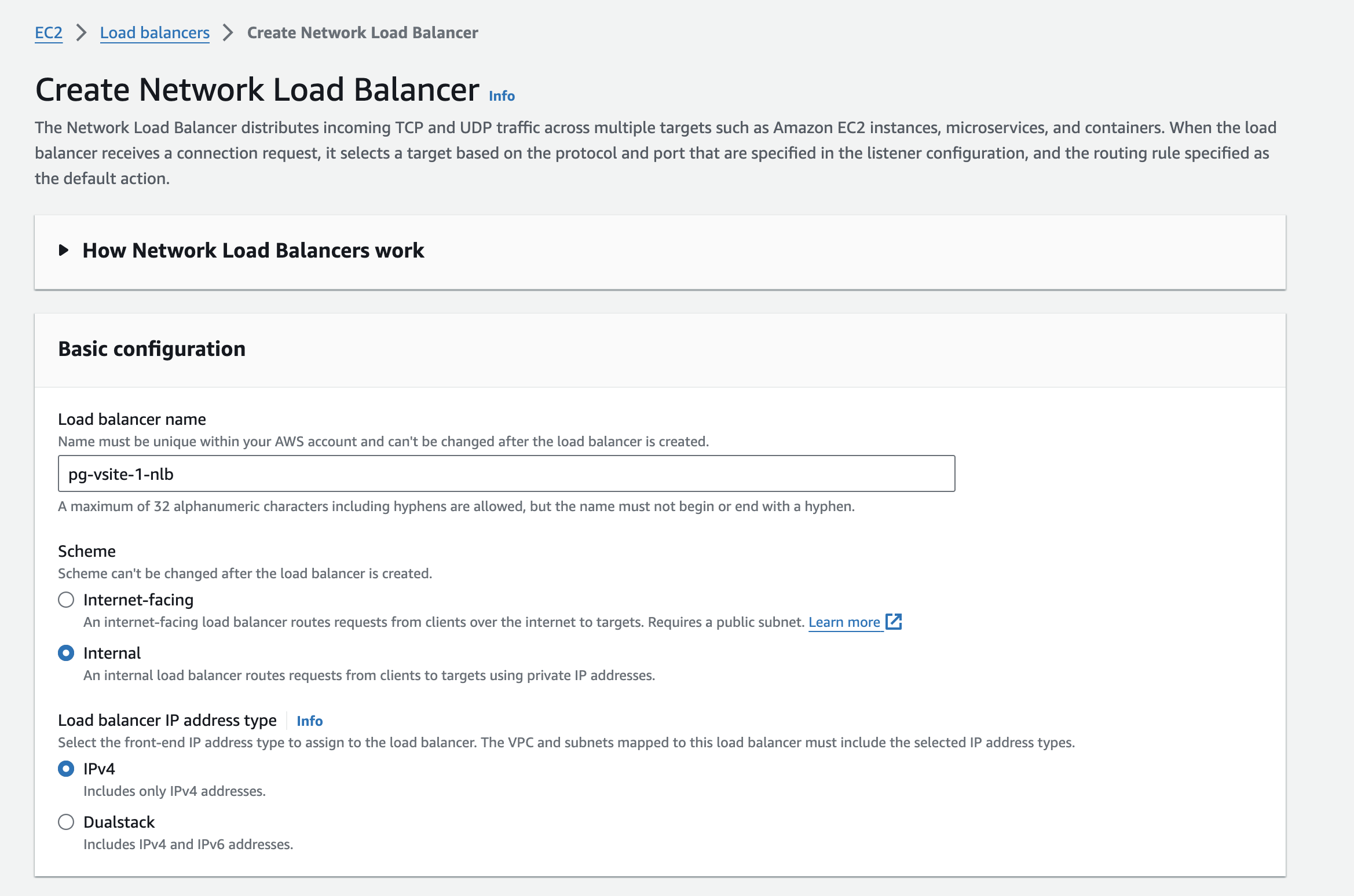
Figure: AWS NLB VIP Internal
- Provide all the necessary information, like the VPC and subnets that contain the CE SLI interfaces.
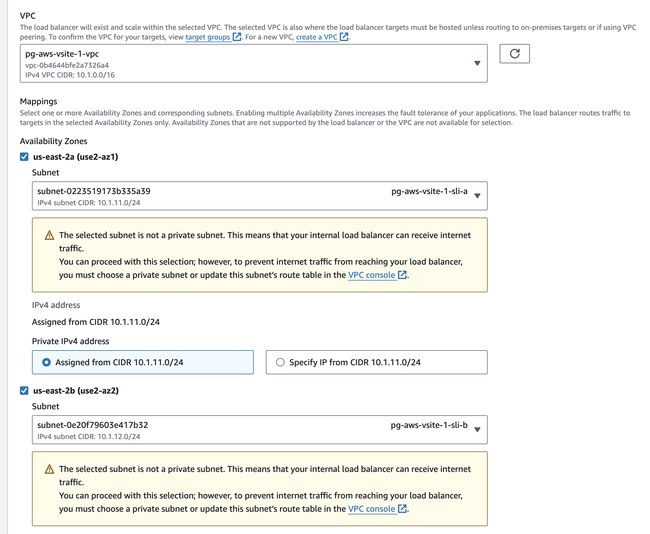
Figure: AWS NLB Network Subnets
- Define the security group and TCP listener port (TCP 80). Note that the security group must allow listening on a port (in this case, TCP 80).
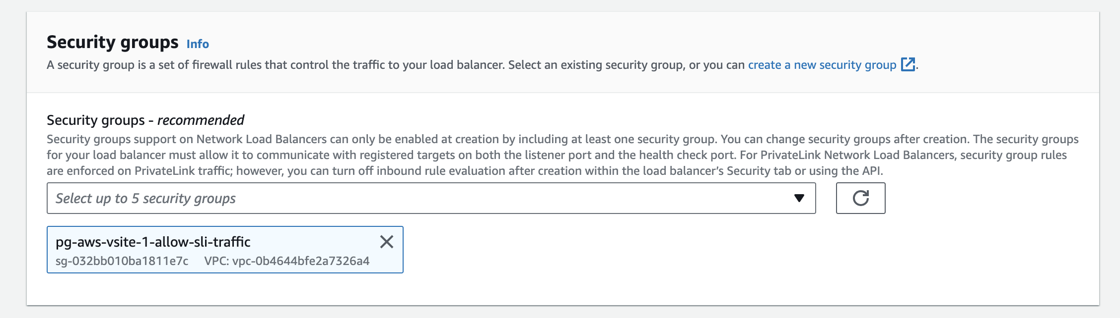
Figure: AWS NLB Security Group
Step 3:
- Define the target group that points to the F5 Distributed Cloud VIP IP addresses.
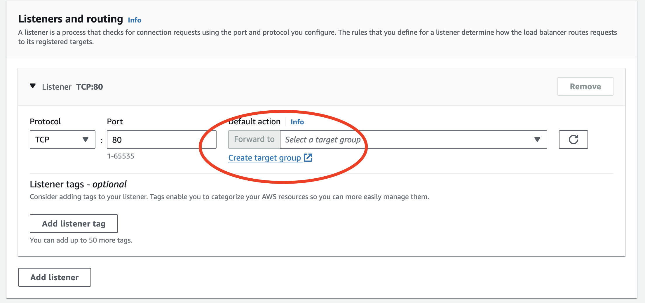
Figure: AWS NLB Target Group
- Choose an IP address-based target, as the F5 Distributed Cloud CE has multiple interfaces.
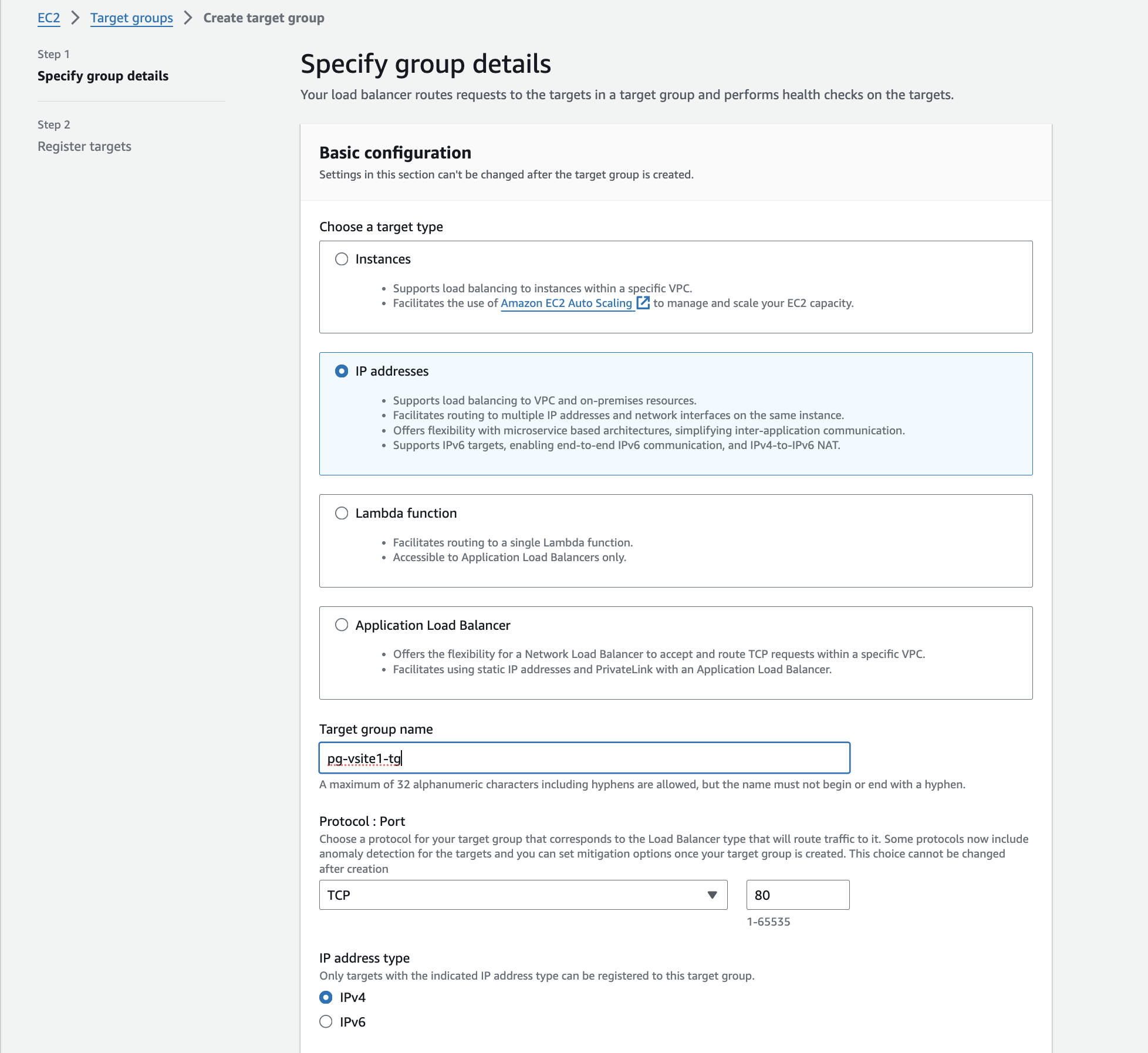
Figure: AWS NLB IP Address Target
Step 4:
- Locate the Site Local Outside (SLO) interface IP addresses for the CE sites. Follow these steps in F5 Console:
- In the Multi-Cloud Network Connect workspace, navigate to Overview > Infrastructure > Sites.
- For your CE sites, identify the SLI interfaces. Note the INSIDE IP addresses for each CE.
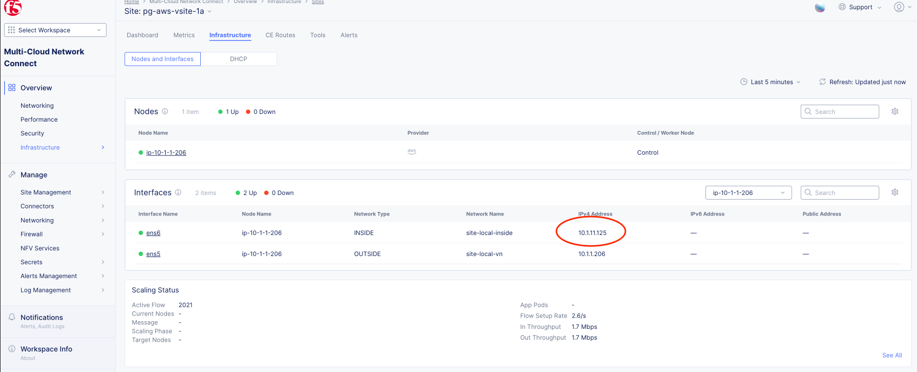
Figure: CE Site SLI Interface IP Address
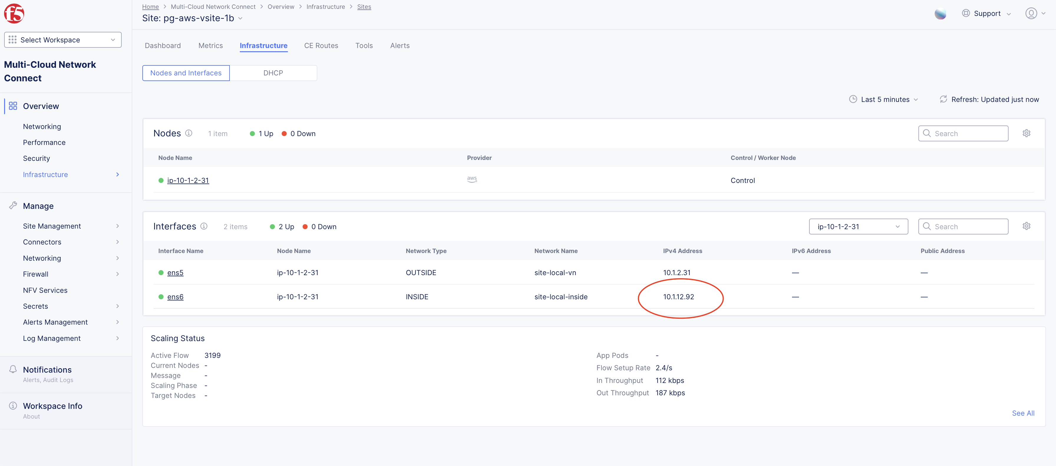
Figure: CE Site SLI Interface IP Address
- To specify the SLO IP addresses as targets, select Include as pending below.
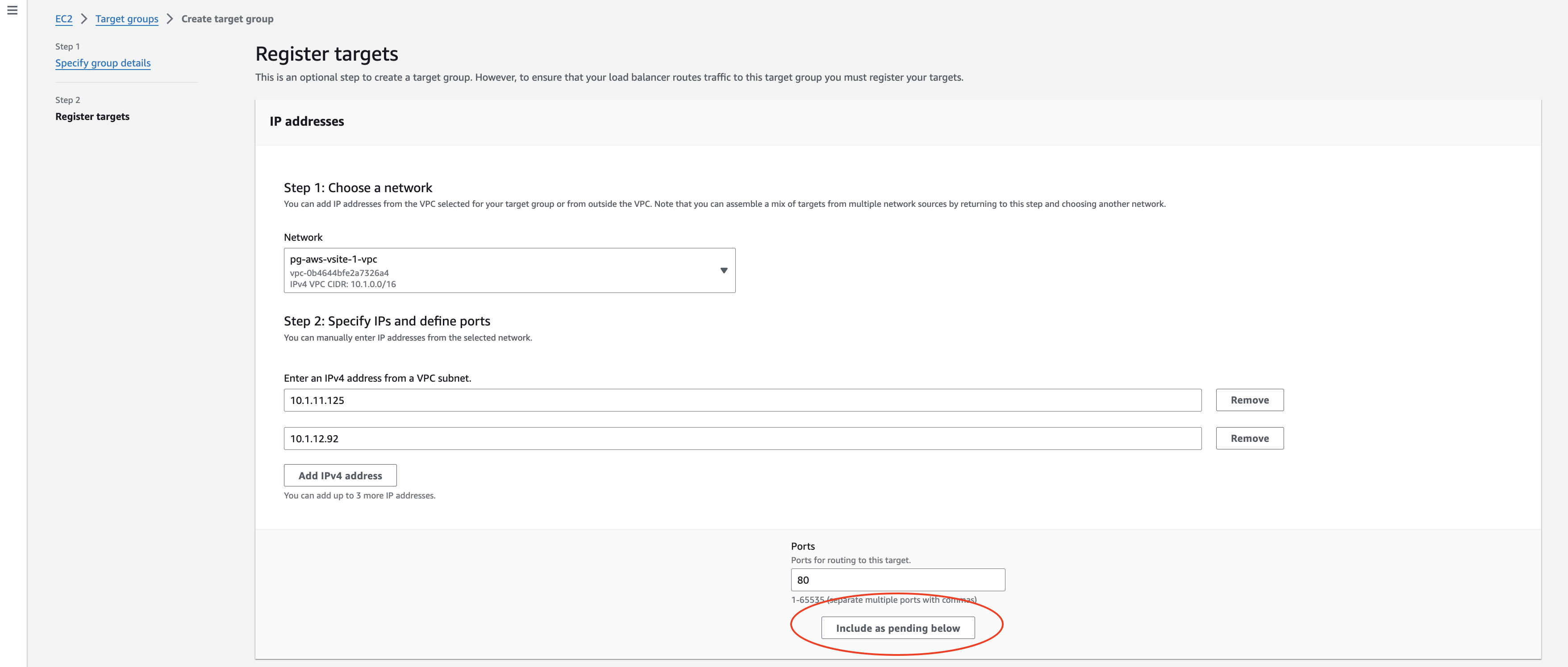
Figure: Specify SLO Interface IP Addresses
-
After you add both IP addresses, select Create target group.
-
Verify the IP addresses under Registered targets section.
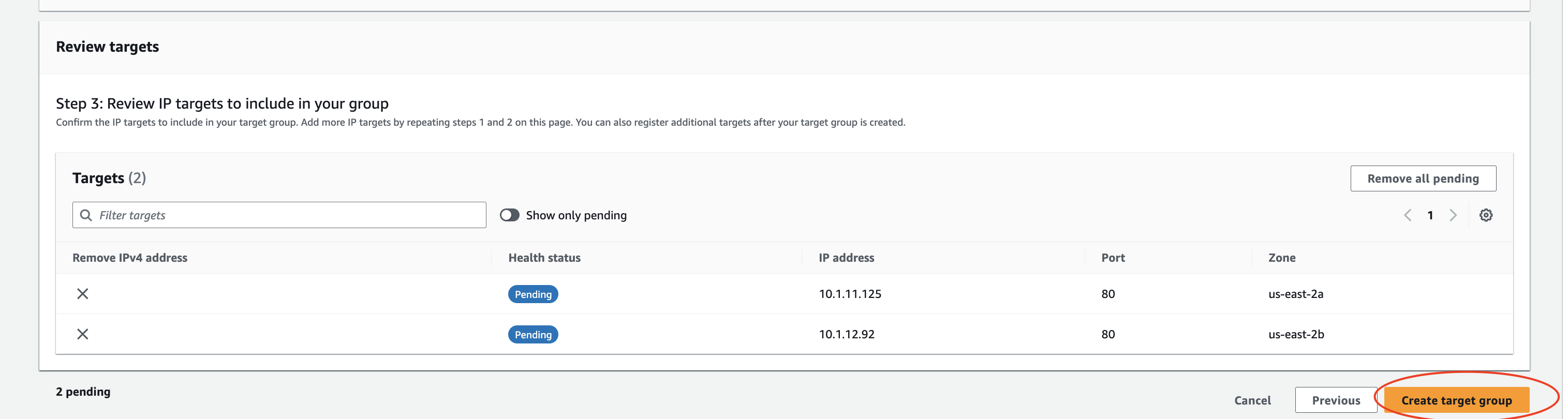
Figure: Verify SLO Interface IP Addresses
-
In the AWS Network Load Balancer window, select Refresh Target groups and choose the previously created target group.
-
Review the listeners and target group IP addresses, and then select Create load balancer.
Step 5:
-
Enable cross-zone load balancing to distribute traffic across availability zones:
-
In the Network Load Balancer settings, select on Enable cross-zone load balancing.
-
As a good practice, enable health checks to validate per CE site VIP reachability by AWS NLB.
-
Configure Azure Network Load Balancer
Create an Azure NLB using the steps in this section.
To expose F5 Distributed Cloud CE VIPs to an Inside or Segment network, an Azure NLB with a frontend Internal IP is required.
Step 1:
-
In your Resource Group, create a new resource of type NLB.
-
Ensure that the Type is set to Internal.
-
Create the SLI frontend IP address.
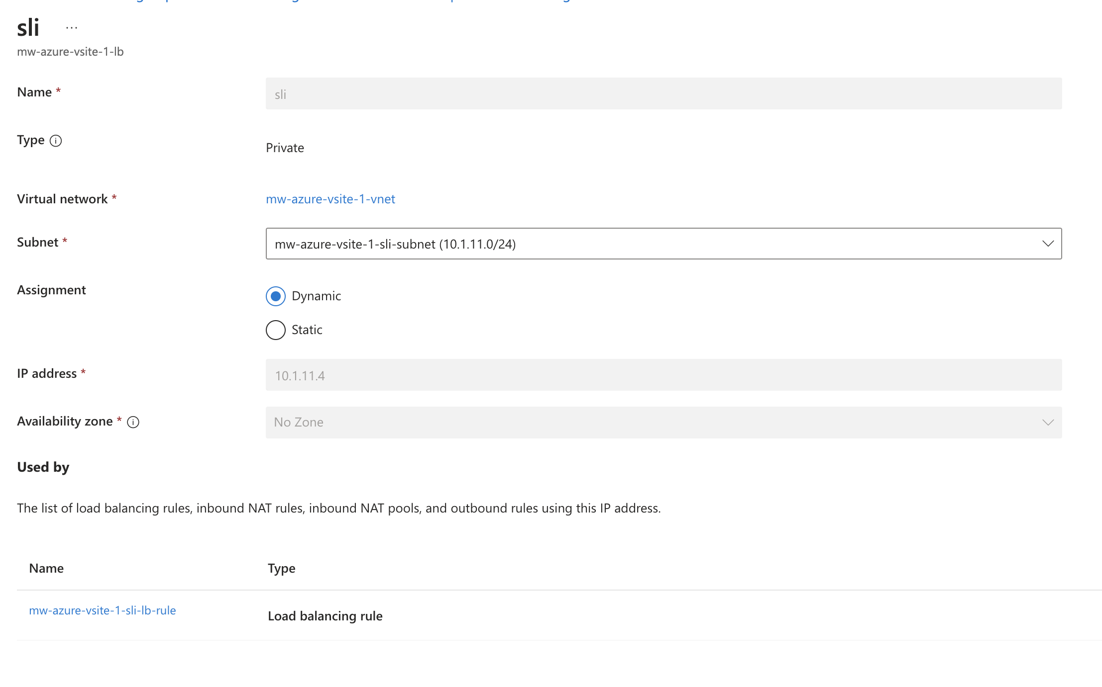
Figure: Azure Frontend IP Address
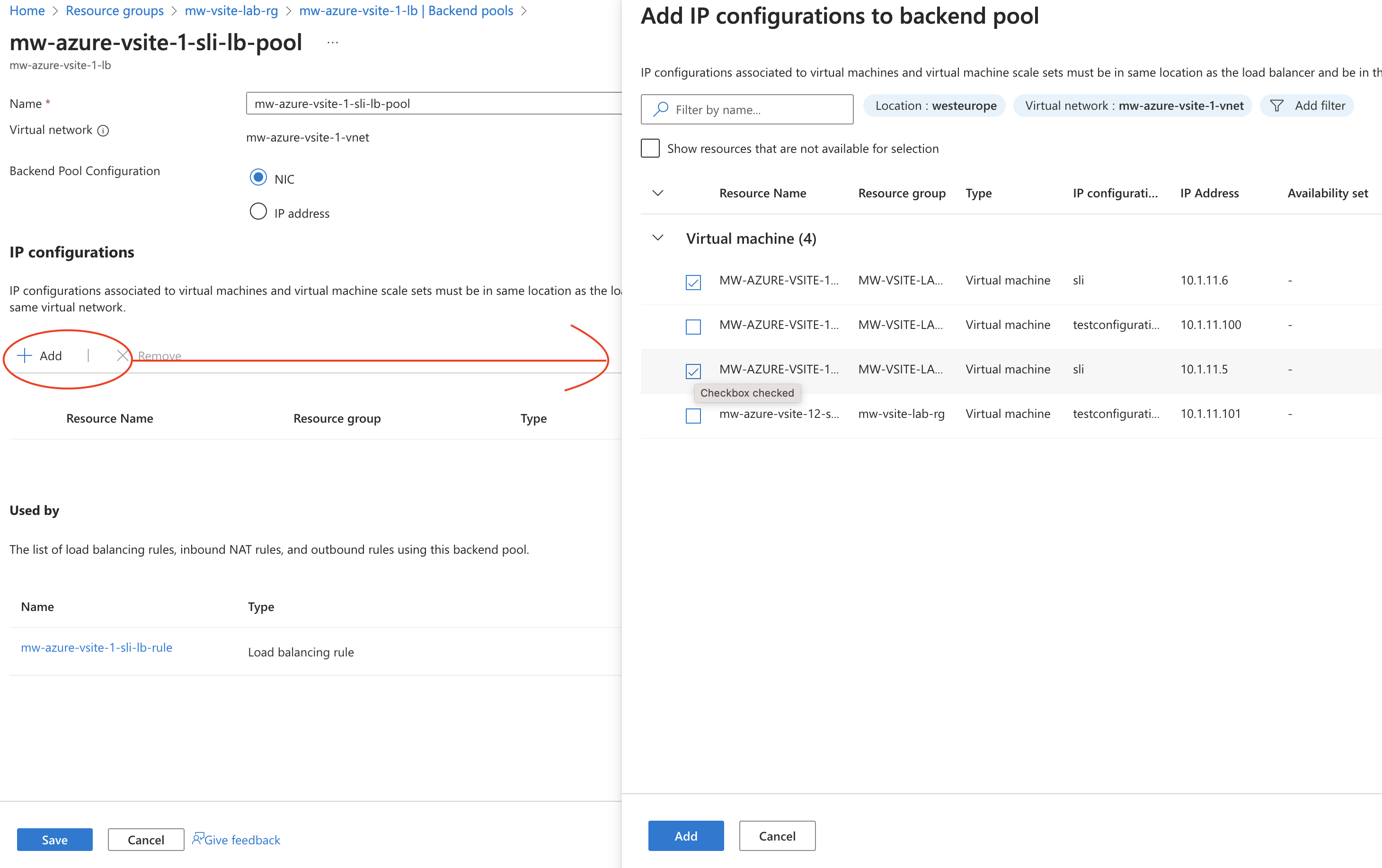
Figure: Azure Frontend IP Address
Step 2:
- Add load balancing rules.
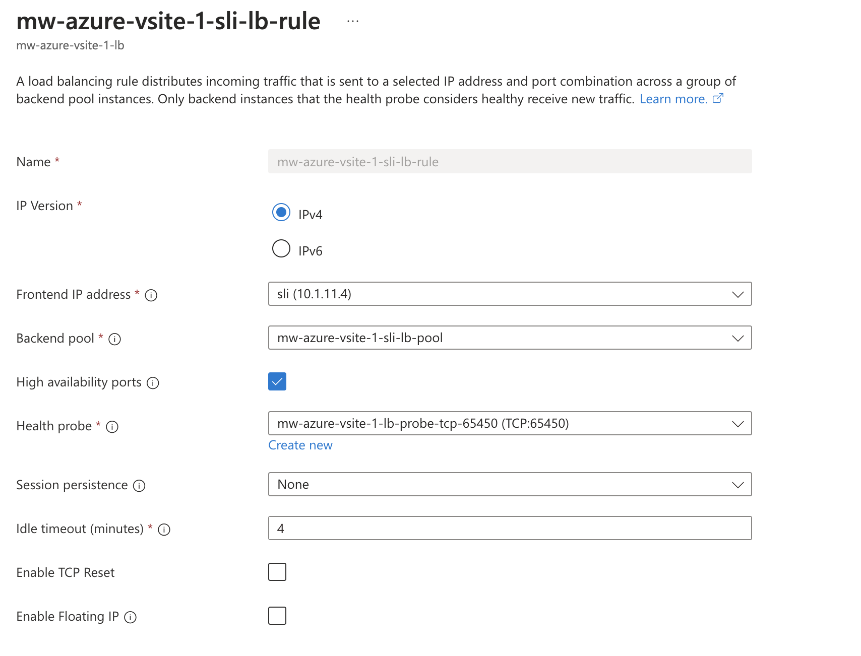
Figure: Azure Load Balancer Rules
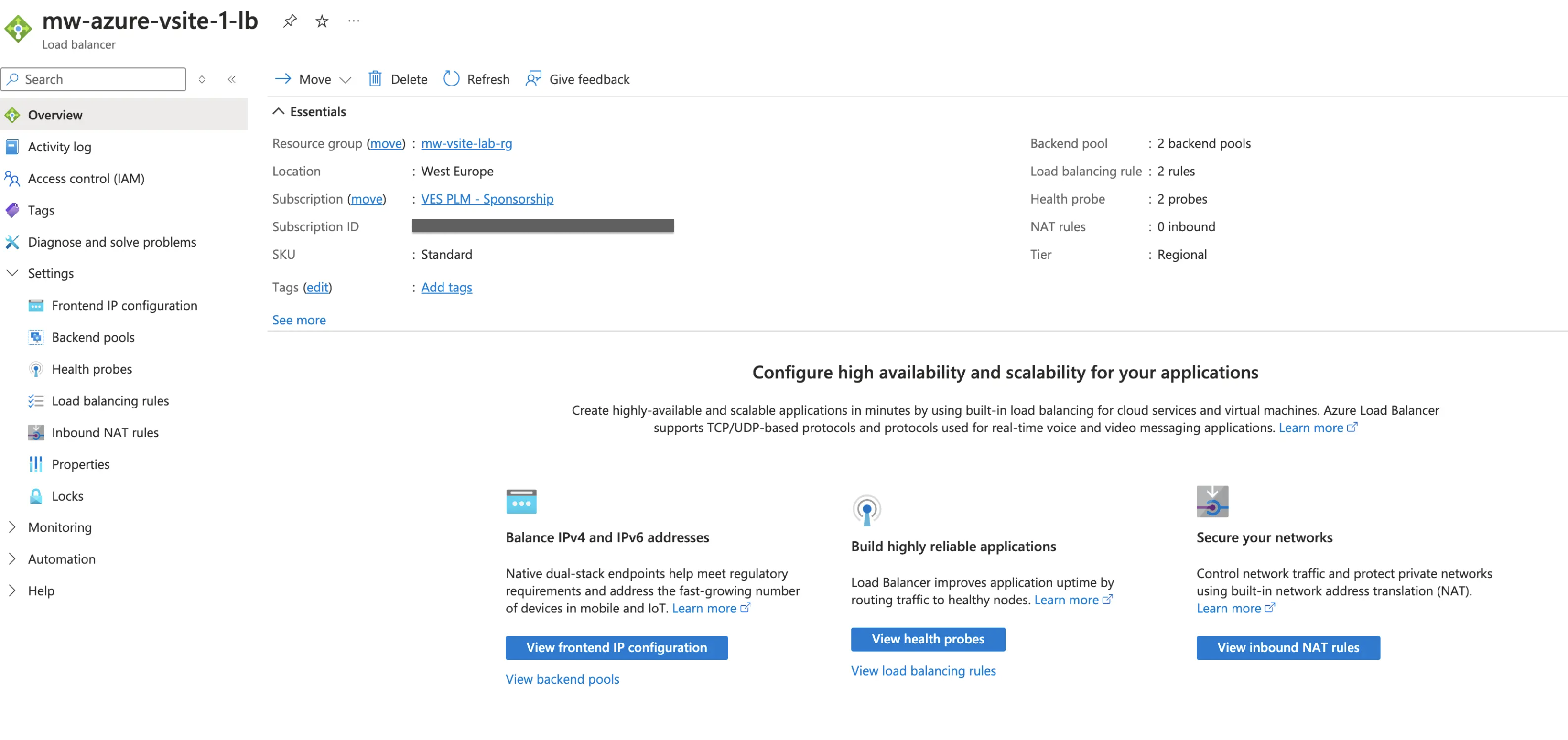
Figure: Azure Load Balancer Summary
- Optionally, add health probes to actively monitor the health of Distributed Cloud VIP addresses.
Configure GCP Network Load Balancer
Use the steps in this section to create a GCP NLB. The NLB targets the inside interfaces of the CE sites.
Step 1: Create network endpoint groups.
-
In GCP Console, navigate to Compute Engine > Settings > Network endpoint groups.
-
Select Create network endpoint group and configure as below for CE Site 1:
- Provide the name.
- From the Network endpoint group type menu, select Zonal NEG.
- Select the Endpoint types as GCE_VM_IP.
- In Network, select the VPC where the CEs are deployed.
- In Subnetwork, select the SLI subnet.
- In Zone, select the zone where the CE Site 1 is deployed.
- Select Create.
-
Select on the newly created network endpoint group, and then select Add network endpoint.
-
Select the VM instance for CE Site 1 and then select Create.
-
Repeat the steps above to create another network endpoint group for CE Site 2.
Step 2: Create NLB.
-
In GCP Console, navigate to Networking > Network services > Load balancing.
-
Select Create load balancer.
-
Select Type of load balancer as Network load balancer. Select Next.
-
For the Proxy or passthrough option, select Passthrough load balancer. Select Next.
-
For the Public facing or internal option, select Public facing (external). Select Next.
-
On the Create load balancer step, select Configure.
-
On the NLB create wizard that opens, configure below properties:
- Provide the load balancer name.
- Select the region where the CEs are deployed.
-
For the Backend configuration, provide the following properties:
- Backend type: Zonal network endpoint group
- Protocol: TCP
- Backends: Add new backends and select the network endpoint groups created in the previous step.
- Health check: Create a new health check for TCP port 80.
-
For Frontend configuration, provide the following properties:
- Provide a name for the VIP.
- IP version: IPv4
- Subnetwork: SLI subnet for CEs
- Internal IP purpose: non-shared
- IP address: Reserve a new static internal IP address.
- Ports: Multiple
- Port numbers: 80, 443
- Global access: Disable
-
Review the configurations and then select Create.
Failover Optimization – Outlier Detection
Origin server failure detection is handled by health checks, which actively monitor the availability of services. These checks are deployed on the sites where the origin servers are defined rather than on the CE Site hosting the load balancer VIP.
If a Site, such as Site2a, becomes unavailable, the active health checks do not immediately inform the load balancer on Site1 that the origin servers are inaccessible via Site2a. Instead, the origin servers are only removed from the load balancer pool once the global controllers confirm that the Site is down.
This process generally takes 110-120 seconds. In some scenarios, this delay may be too long, necessitating optimization to minimize downtime. The Outlier Detection feature can assist in addressing this issue effectively.
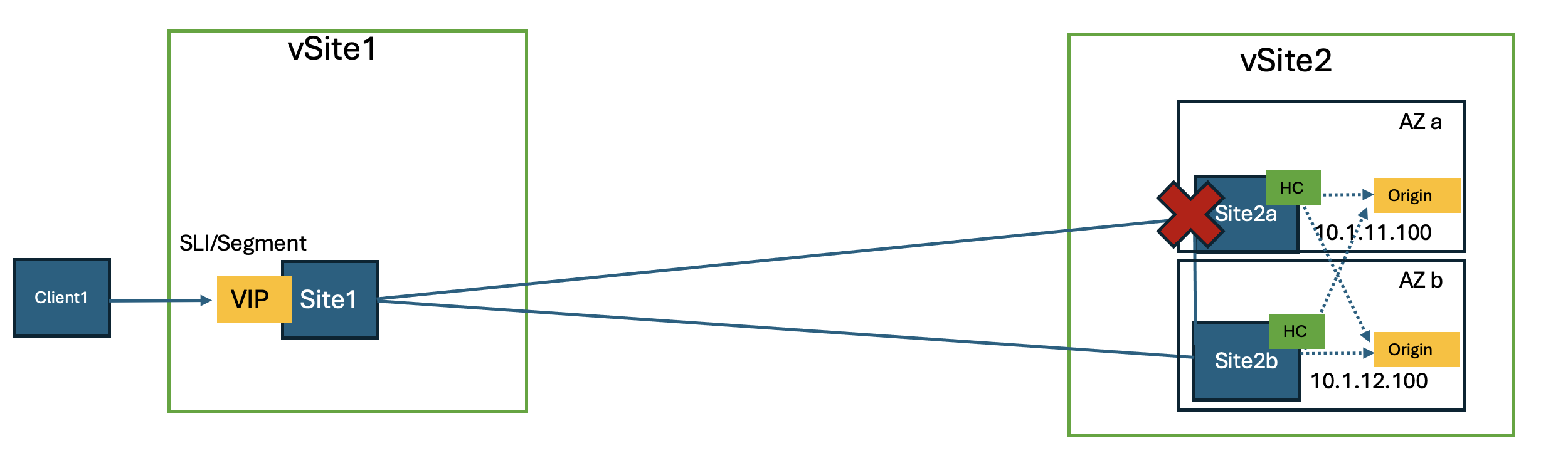
Figure: Failover Optimization – Outlier Detection Diagram
Configure Outlier Detection
Note that some potential drawbacks for this feature include passive health checks, working only with HTTP/HTTPs, and requiring traffic be sent to production to a broken node, to detect if it is operational.
-
In the Multi-Cloud App Connect workspace, navigate to Manage > Load Balancers and then select Origin Pools.
-
For your load balancer, select ....
-
Select Manage Configuration > Edit Configuration.
-
In the Other Settings section, select Configure.
-
From the Enable/Disable Outlier Detection menu, enable Outlier Detection.
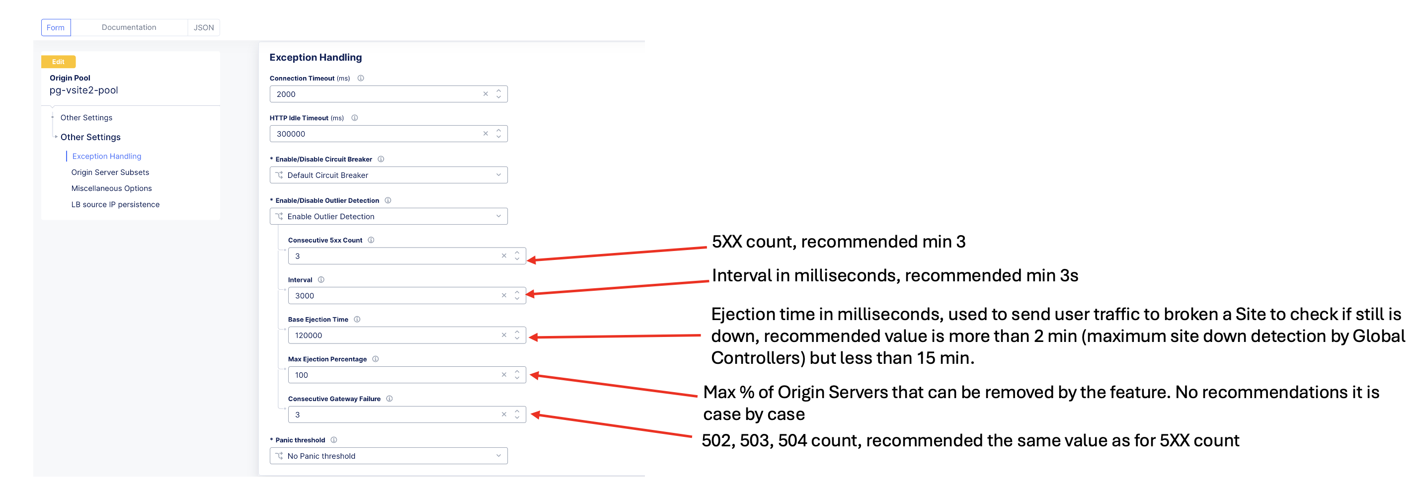
Figure: Enable Outlier Detection
Concepts
On this page:
- Objective
- Introduction
- Prerequisites
- Procedure
- Configure Virtual Site
- Deploy CE Sites
- Create Virtual Site Object
- Assign CE Sites to Virtual Site
- Configure Origin Pool Using Virtual Site
- Use Cases
- Public Application Delivery Using Regional Edges
- Configure Load Balancer
- Public Application Delivery Using Customer Edges Grouped as a Virtual Site
- Configure Load Balancer
- Public Application Delivery Across Customer Edges Grouped into a Virtual Site
- Configure Load Balancer
- Failover Optimization – Outlier Detection
- Configure Outlier Detection
- Concepts